I’m currently attending the iGEM synthetic biology competition’s “Jamboree”, where all the teams present their results. It is a big conference (about 3000 attendees this year, representing about 300 teams), so a bit overwhelming.
One thing that surprised me was that the UCSC team of 17 undergraduates was listed as an “overgrad” team, rather than an “undergrad” one. It turns out that the classification has nothing to do with student status or education:
There are 3 sections in iGEM 2016:
- Undergraduate: all student team members are age 23 or younger on March 31, 2016
- Overgraduate: one or more student team members are older than 23 on March 31, 2016
- High School: all student team members are high school students on March 31, 2016; includes students who graduate from high school spring 2016
The age constraint seems like a very strange way to divide undergraduates from graduate students. It does not work well in countries where there is mandatory military or civil service before college, and it does not work well for minorities and the poor in the USA. I think that the problem is that the people defining the sections have a very narrow view of what it means to be an undergraduate—one that is colored by their teaching at elite private universities in the US.
The Common Data Set that each college in the US has to publish provides information about the percent of undergrad students age 25 and older at different institutions (question F1 on the form). For example, UCSC reports 4% of undergrads are 25 and older, UCLA reports 5.1%, UC Berkeley and University of Illinois report 6%, Cal Poly reports 3%, San Jose State reports 20%, while Stanford and MIT report only 1%. I have not looked at many colleges, but there seems to be a clear trend that elite private schools are much less likely to be familiar with older undergraduates than public schools, and that higher status public schools have (like UC) have fewer older students than good, but slightly lesser status schools like San Jose State. (I’ve not found a site that allows rapid summaries of the Common Data Set across many institutions—colleges are required to report the information, but no one seems to be making it accessible other that by one-college-at-a-time lookup—if someone knows of a good site for exploring the data, please let me know.)
Looking at the schools most attended by minorities and poor students in the US—the average age of a community college student is 29 [http://www.aacc.nche.edu/AboutCC/Trends/Pages/studentsatcommunitycolleges.aspx].
By using age as a cutoff, iGEM is being quite elitist—their definition of “undergraduate” only matches the demographics at elite private schools.
I asked about the reasons for the age cutoff, and it seems like some teams were complaining about having to compete against teams that had 35-year-old students on them, and that this was somehow unfair. I find this mystifying. How is it that a student who worked in a warehouse or tending bar for 15 years before finally being able to afford college has an unfair advantage over a student whose parents had the money to send them to college immediately?
I’m a bit more sensitive about re-entry students than many college professors, perhaps because of my mother. Her college education was interrupted by World War II, and she did not get an opportunity to go back to college until her 50s. I am very grateful to the US system of community colleges that allowed her to return to college at that age and earn an AA degree. Being told that she would not have qualified as a “real undergrad” is personally offensive.
Coming up with a simple rule that can be applied uniformly around the world to distinguish undergraduate from graduate students is not easy, but I think that a simple age cutoff is one of the poorer choices that could have been made. Years of education since age 5 (to avoid cultural differences in when schooling starts) might be a better choice. Certainly the reasons given for the age criterion (to make the competition fair to undergrads) reveals a real misunderstanding of who undergraduates are outside the elite US colleges.


 as my coordinate, with current $i = \dot q$ as its derivative with respect to time. In all but the simplest circuits, there will be multiple charges or currents involved, which I’ll distinguish with subscripts.
 is the difference between kinetic and potential energy of the system. The potential energy will be the energy stored in capacitors,
  , and the kinetic energy the energy in the inductors,
  . (Note: that is only self-inductance. If we have mutual inductance
  between two inductors, we need to use
  for the kinetic energy—I’m a bit confused by that, as we could have negative kinetic energy. I rarely use inductors or transformers in my electronics, so I’ve not had to work out my confusion yet.)
 is the power dissipated by the resistors in the system:
  .
. is the vector input to the system needed to make the energy balance work out. By using charge for each coordinate, the units here will be volts.
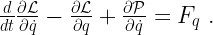
 , which is indeed volts.
 , which is also volts.
 , which is again volts (Ohm’s Law).
 or
or  has to be associated with each component of the system, and what voltages the
  correspond to. I think that will be easiest if I have some specific circuits to work with. Let’s start with a very simple one:
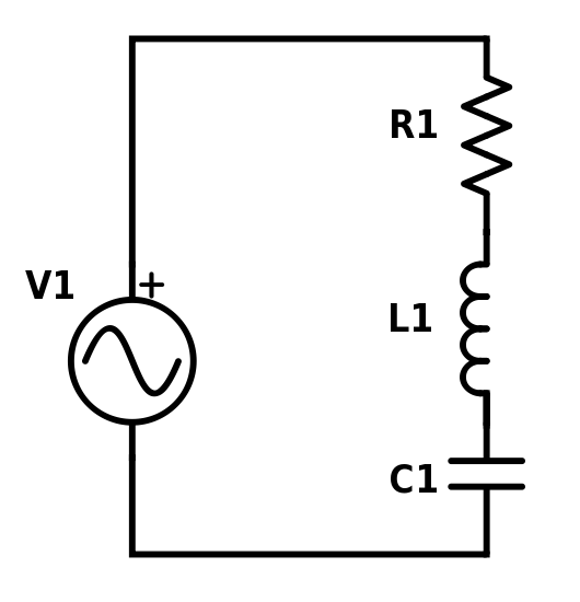
 , so that the current flow
  is clockwise in the schematic. We get the Lagrangian
 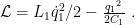 The power dissipation is
  , and taking the derivatives gives us
  , which is the voltage for the voltage source.
 , there is no kinetic energy (no inductors), and the dissipation is
  . Taking the derivatives of the Lagrangian gives us
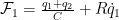 and
and .
. and
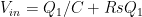
and  terms are 0 (modeling the voltmeter as a perfect infinite impedance), giving us the usual formulas for the input and output voltage, in terms of the charge on the capacitor:
 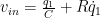 and
and  .
. and
and  , which gives us the transfer function
  , as expected. (Plug in
  to get the usual format in terms of angular frequency.)
")
 or hardback ($198)")

