Digilent has announced a price reduction on the Analog Discovery2 (back to pre-pandemic prices: $299 for anyone and $199 academic pricing). The impetus for the price reduction is that they have brought out the Analog Discovery 3 ($379 and $249 academic), which has slightly better specs (25% higher sampling rate, 14% higher current power supply, double the buffer size). The software and hardware interfaces are otherwise identical.
2023 July 6
2021 January 9
One week into new quarter
We’re one week into the new quarter (10% of the way through!) and the course is going ok. Most of the students have finished the first-week lab, which consists of installing a lot of software and soldering headers onto a Teensy LC board.
The software they had to install was
Of course, each piece of software has its own installation idiosyncracies, different on Windows, macos, and Linux. Some people even bumped into some problems because of running old versions of macos or Python (which were luckily cleared by upgrading to slightly newer versions).
The soldering was a bigger problem, because many students plugged in their cheap irons and left them on for a long time without tinning the tips. The result was a sufficient build-up of corrosion that that they could not then tin the tips—even using a copper ChoreBoy scrubber to clean the tips didn’t help in some cases. In the in-person labs, I often spent most of the first week labs cleaning soldering iron tips that students had managed to mess up, but I can’t do that online. This was not such a problem last quarter, as most of the students knew how to care for soldering irons from the first half of the course, but it may be a bigger problem this quarter, as most of the students have never touched a soldering iron before. Some of the ones who are living here in town may be contacting the lab staff to see if they can get access to tip tinner or get some help cleaning their irons. Those further away may be buying tip tinner on their own—I had not included it in kits, because I nad not expected so many to need it and it costs $8 apiece.
Grading is going fairly well. My grading team and I have had two Zoom meetings so far (for Homeworks 1 and 2) and I graded Quiz 1 by myself, so we are keeping up with the grading. He have Homework 3 and Prelab 2a (there is no Prelab 1) both due Monday morning, and we’ll try getting them graded Monday night. We’re having to do most of our grading in the evening, because one of the graders is living in China, 15 time zones away, and none of us in California is an early morning person.
In other news, I’ve finally finished clearing the blackberries and ivy from behind the garage (a project I started about 2 years ago). I’ll probably find some more when I cut back the kiwi vine (an annual winter project, in addition to frequent minor pruning during the summer). I think I either need to get some female kiwi vines and an arbor for them or uproot the male kiwi. There is really not much point to having just a male kiwi intent on taking over a big chunk of the yard.
There are still a lot of blackberry roots out there that will sprout new vines. I’ll try uprooting them where I have access (not where they are coming through the cracks in the concrete), but I’ll probably have to do a monthly sweep of the yard to remove blackberries for the rest of my life in this house.
2020 October 28
Analog Discovery 2 power-supply noise
Last night and this morning I spent some time investigating the noise on the power supplies of the Analog Discovery 2, because some students were having trouble with power-supply noise on their audio amplifiers (an inherent problem with biasing the microphone with just a bias resistor to the power supply).
I looked at the positive supply set to +3.3V using oscilloscope Channel 1, and saw a fluctuation in voltage that was not too surprising for a switching power supply (though the switching frequency seemed ridiculously low). The power supply is specified to stay within 10mV of the desired voltage, and the voltage seemed to be doing that.
I know that some switching power supplies shut themselves off under low-load conditions, to retain efficiency at the cost of adding low-frequency ripple to the output, so I tried running the power supply with different load resistors. I did the sampling at 400kHz and took FFTs of the signal (exponential averaging of RMS with weight 100, Blackman-Harris window).
Here are the signals:

The signals show quite a bit of oscillation without a load, but decreasing with increasing load.
Here are the spectra from the Fourier transform (removing the DC spike):

The spike around 57.2kHz is present with all loads and remains at the same frequency even if I change the sampling rate, so is probably the underlying frequency of the switching power supply.
The rather large fluctuations in the audio range are probably the result of the power supply shutting itself off when there is low current draw. Drawing 10 mA is not quite enough to prevent this shutdown, but 27.5mA seems to be enough.
So there seem to be at least three solutions for students having problems with power-supply noise:
- Taking enough current from the power supply that the power supply doesn’t shut itself down. This is a rather fragile technique, as other sources of power-supply noise (such as noise injected by the power-amplifier stage in a later lab) will not be eliminated.
- Using a transimpedance amplifier instead of a bias resistor to bias the mic. The bias-voltage input to the transimpedance amplifier can have a low-pass filter to keep it clean.
- Putting a low-pass filter (with a small resistor and large capacitor) between the power supply and the bias resistor. The resistance of the filter adds to the resistance for the DC bias calculation, but not to the resistance for the i-to-v conversion.
2020 June 5
Compensation in impedance analyzer
The Analog Discovery 2 has an impedance analyzer that includes short-circuit and open-circuit compensation to correct for the impedances of the test fixture, and I’ve been thinking about how that might be computed internally. The open-circuit and short-circuit compensation can be applied independently or together, but each requires making and recording an impedance at each frequency for which impedance analysis is done.
Since there are three impedances that are measured (open-circuit, short-circuit, and device-under-test), I came up with two circuits that could model the test setup:

The measurement is made at the two ports, and Z_DUT is the device being measured—the other two impedances are parasitic ones of the test fixture that we are trying to eliminate.
Let’s look at the short-circuit compensation first. For the first model, if we replace Z_DUT with a short circuit, we measure an impedance of 


For open-circuit compensation, in the first model we get 


If we do both compensations, we can use either model, but the corrections we end up with are slightly different.
For the first model, we have 


We can simplify that to 


For the second model, the algebra is a little messier. We have 


We also have 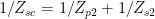


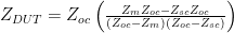

Once again, when
We can make the two formulas look more similar, by using the same denominator for both, making the formula for the first model

That is, the only difference is whether we scale by 

For example, for the following compensation measurements using the flywires, a breadboard, and some short leads with alligator clips to make the test fixture

the choice of compensation formula would make a 3% difference is the reported impedance at 10MHz. Notice that 


Because the open-circuit impedance here is much higher than the input impedance of the measuring oscilloscope channel, I believe that corrections have already been made for known characteristics of the oscilloscope channels.
The exact values of the
2019 December 19
Macos 10.15 Catalina vs PteroDAQ
I had a serious scare today.
First, I found out that the software for my Analog Discovery 2 was crashing on the MacBook Air that I will be using for lectures and lab next quarter. It behaved normally at first and then crashed for no discernible reason after a couple of minutes. I figured that the problem was probably related to the macos “upgrades” I had done recently, so I checked the Digilent website, and they had just posted a new version of the software last week, addressing the changes that Apple had made to their USB stack (which broke almost all 3rd-party software and a fair amount of Apple’s own software). I downloaded the new version of Waveforms from the Digilent site and everything worked again.
But any changes to the USB stack are likely to break the code that PteroDAQ uses for finding what devices are connected, so I checked PteroDAQ with my usual setup. The GUI for PteroDAQ did not list the Teensy board as it used to do, and PteroDAQ couldn’t run! I spent a long time with ioreg trying to figure out how to modify macgetports.py to find the device again. The Teensy board was visible as an AppleUSBDevice and AppleUSBInterface, but not as an IOSerialBSDClient as it used to be. I could not figure out how to open it as a serial port!
Now my usual setup involves going through a USB 2.0 hub (in the Cerebrus cable), so I dug around in my drawer of parts until I found a plain USB-micro data cable. Hooking up the Teensy board directly with that cable did show an IOSerialBSDClient interface, and PteroDAQ worked fine. So the problem is just that connections through the USB 2.0 hub are not made the same way they used to be—the serial connection no longer is visible the way it used to be.
I’ll enter an issue for this on the PteroDAQ GitHub, but I won’t try to fix it unless it turns out that modern USB C-USB 3 docks exhibit the same problem.

")
 or hardback ($198)")

