I don’t usually give exams in my courses any more, because I’m more interested in what students can do when they have time and resources than what they can do on toy problems under resource limitations. But if students don’t do the homework, then they don’t learn the material, so I threaten each class that if too many students don’t turn in the homework, I’ll have to add a quiz (worth as much as one of the lab reports, each of which is equal to all the homework) to the course.
This quarter I had to follow through on that threat, because 12% of the class had turned in half or less of the homework (and by that, I don’t mean answered half the questions—I mean turned in nothing at all for half the assignments). A quarter of the class had not turned in 25% or more of the assignments.
I gave the quiz yesterday, with 6 easy questions that only tested the very basic material: single-pole RC filters (passive and active) and negative-feedback amplifiers. I told students ahead of time (and on the exam) that they could use the Bode approximations (the straight-line approximations to the gain of the RC filters) and we even reviewed them in class last week. There were 60 points possible on the test, and none of the questions were design questions—they were almost all of the form “what is the corner frequency?” or “what is the gain of this circuit?”.
There are a small number of students in the class whose probity I have reason to question, so I took steps to reduce cheating that I would not normally bother with: I made up two versions of the test (same schematics, but different component values) and alternated them in the piles passed along each row. I also had the students sit in different rows from usual, reversing front and back of the room, with the front row reserved for latecomers. I’ve noticed a high correlation between good homework grades and people being on-time and in the first two rows, so I had those students sit in the back row, where no one would be able to copy from them.
I normally figure that a test is appropriately long if an expert can do it in about a quarter of the time allotted. So I made up the keys for the test while the students were taking it. Working through one form with the Bode approximations took about 5 minutes. Doing exact computation with the formulas for series and parallel impedances and complex numbers using only real-number arithmetic on my calculator extended that by another 15 minutes. The students had 63 minutes, so the exam was too easy if the students used the Bode approximations (as they were told) but a little too hard if they worked just from the fundamentals of complex impedance and negative-feedback amplifiers. As a consequence, I decided to give bonus points for exact computations of the gains that didn’t use the Bode approximations, though the class was not informed of this bonus, because I didn’t want them to waste time on the tiny bonus. (The differences in answers were small, because I had deliberately asked for gains only at points well away from the corner frequency, so that the Bode approximations would be good.)
Even if students really didn’t understand complex impedance or RC filters, 39 of the 60 points could be earned with just DC analysis of the negative-feedback amplifiers and knowing that capacitors don’t conduct DC. So I was hoping that students would do better on these very easy questions than they did on the harder design questions of the homework. As a confirmed pessimist, though, I expected that students would show almost exactly the same distribution on the test that they showed on the homework, with the middle of the class being around 20 out of 60 points and showing serious misunderstandings of almost everything, with a long tail out to one or two students who would get almost everything right. I also expected that the correlation between the homework scores and the quiz scores would be high.
So what happened? First, I saw no evidence of any cheating (not that I had expected any), so that is one worry removed. Second, my pessimistic assumption that students really were not learning stuff that they had done many times in homework and in lab was confirmed:
Here is a stem-and-leaf plot of the scores:
OO: 3
05: 6889
10: 011112444444
15: 555667777899
20: 00111112223344
25: 677999
30: 12224
35: 5678
40: 00444
45: 67
50: 01
55:
60: 2
The median is indeed 21 out of 60, as I feared. At least no one got a zero, though the scores at bottom indicated complete failure to apply the basics of the course.
Most students could compute a corner frequency from a resistor and capacitor, but few had any idea what to do with that corner frequency. Many students could compute the DC gain of a non-inverting amplifier, though many could not then apply this knowledge to the DC gain of an active filter (which only requires replacing the capacitors with open circuits). A lot of students forgot the “+1” in the formula of the gain for the non-inverting amplifier.
Inverting amplifiers were even less understood than non-inverting ones, with students forgetting the minus sign or trying to use the formula for non-inverting amplifiers.
A lot of student answers failed simple sanity checks (students were having passive RC filters with gain greater than 1, for example).
Very few students used the Bode approximations correctly, and many tried the exact solution but either couldn’t set up the formulas correctly or couldn’t figure out how to use their calculators, often getting numbers that were way, way off. Others seem to have ignored the complex numbers and treat  as if it were
  .
.
One disturbing result was how many students failed to recognize or understand a circuit that they have designed in three different labs: a voltage divider and unity-gain buffer to generate Vref, combined with a non-inverting amplifier. I asked for the output voltage as a function of the input voltage (both clearly labeled on the schematic). This was intended to be almost free points for them, since they had used that circuit so many times, and the formula they needed was one of the few formulas on the study sheet: 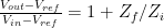 . The frequent failure to be able to fill in the blanks of this formula for a circuit that they have used several times in design makes me question whether the students are actually learning anything in the course, or if they are simply copying designs from other students without understanding a thing. (Note: the extremely poor performance and group-think duplication of ludicrously wrong answers on pre-lab homework this year has also lead me to the same question.)
Did the quiz tell me anything that the homework had not already told me? Here is the scatter diagram:

Pearson’s r correlation is 0.539 and Kendall’s tau is 0.306, so the homework and quiz scores are highly correlated. There are a few outliers: a diligent student who bombed the quiz and a student who has turned in few of the homeworks who actually understands at least the easy material. The points have a small amount of noise added, so that duplicate points are visible.
The high correlation between the quiz and the homework mostly confirmed my prior belief that the quiz would not tell me much that is new, and that the homework grades were pretty reflective of what students had learned. I will want to talk with a few of the most extreme outliers, to find out what happened (why were students who mostly understood the material blowing off the homework? and why did diligent students who had been doing moderately well on the homework bomb the quiz—is there undiagnosed test anxiety that should be getting accommodations, for example?).
Most of the points that were earned were from students randomly plugging numbers into a memorized formula and (perhaps accidentally) having chosen the right formula and the right numbers. Only a few students showed real understanding of what they were doing, and only one student saw the quiz as the trivial exercise it was intended to be.
It seems that the hands-on active learning that I have been so enthusiastic about is not working any better at getting students to learn the basics than the traditional (and much cheaper) droning lecture that EE uses. I’m not in complete despair about the course, as there is some evidence that students have picked up some lab skills (using oscilloscopes, multimeters, soldering irons, …) and some writing skills (though many are still not writing at a college level). But I’m trying to teach the students to be engineers, not technicians, so I was aiming at them understanding how to design and debug things, not just implementing other people’s designs. Picking up lab skills is not enough for the course.
I need help. How do I reach the lower half of the class? How do I get them to think about simple electronics instead of randomly applying half-remembered formulas? We’ve only got 3 weeks left—I don’t know how much I can salvage for this cohort, but I certainly would like better outcomes next year.


")
 or hardback ($198)")

