I’m planning to sit in on CMPE 118/L (Mechatronics) this fall, and so I started looking over some of the material for the course from previous years. One exercise involved designing a “beacon detector” that signals when it sees an infrared signal modulated with a 2kHz square wave. The exercise calls for an all-analog solution (phototransistor, transimpedance amplifier, active filter, rectifier, peak detector, …), which I plan to do when the time comes, but I got intrigued by the idea of doing an almost purely digital design. That was the motivation for the Goertzel filter blog post.
I decided to take the digital design further and make a beacon detector that not only detects the 2kHz IR beacon, but also indicates what direction it is in. To do this, I wanted 8 phototransistors around a circle, with one every 45°. One can get a crude estimate of the angle from just which detector gets the strongest signal, but with wide-angle sensors one should be able to get finer estimates by looking at the ratio of the signals from two adjacent channels.
Because I was deliberately going for minimal analog design as an exercise, I used just a phototransistor and a pullup resistor for each channel, and a Teensy LC board for all the processing. I chose SFH325FA side-look phototransistors, because they provide a nice, cubical package that I thought would make them easier to align. They are surface-mount components, but with a 2.54mm pitch for the two terminals, they aren’t much harder to solder than through-hole parts.
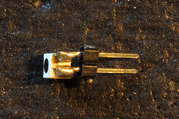
For testing, I soldered one of the SFH325FA phototransistors to a pair of male header pins. This allowed me to experiment with different pullup resistor sizes in different lighting conditions and at different distances from an IR emitter.
My experimentation with different pullup resistors indicated that I could not operate in full sunlight, no matter what size pullup resistor I used—when the pullup was small enough that the phototransistor had sufficient voltage across it in full sunlight, the signal from the IR beacon was too small to be useful. With AC-coupled amplifiers, I could have made it work, but I was committed to nearly pure digital solution. If I had sunlight nearby, but the phototransistor itself was shaded, then I could go up to 22kΩ for the pullup without problems. The limiting factor was then that a very close beacon could saturate the detector, making it hard to determine power ratios. I ended up choosing 22kΩ as my pullup, as I wanted to detect beacons from up to 2m away.
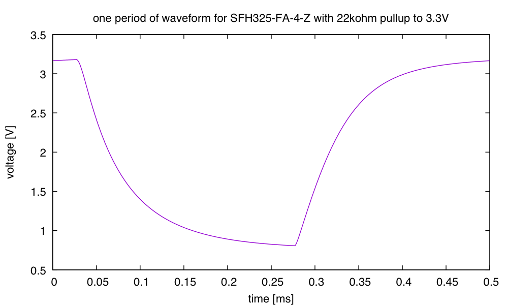
With a 22kΩ pullup and a strong signal, I can get a very clean “shark’s fin” waveform, because of the capacitance of the phototransistor acting with the resistor as a low-pass filter. This low-pass filtering helps remove aliasing artifacts from the sampling by the analog-to-digital filter.
Behind each phototransistor I placed an LED, to indicate which channel had the maximum signal. I charlieplexed the LEDs, so that I needed only 4 I/O pins for the 8 LEDs (I could encode up to 12 LEDs with 4 charlieplex wires). I used WP710A10SGC green LEDs for the indicators, because I had a lot of them around, but it would have been better to use an amber LED with a wide-angle, diffuse case, as the green indicators are only clearly visible over a fairly narrow angle. The current-limiting resistors I used would keep the current low enough even with a low-forward-voltage red LED.
I also added an RGB LED to indicate the overall state—I used a common-anode one, because my son had a lot of them with diffuse cases, which are best for an indicator that needs to be seen from any angle. The RGB LEDs were part of an unidentified lot from China, so I don’t have a part number or specs for them. I hooked them up to PWM pins, so that I could adjust the brightness and color as needed.
I also designed in a connector for SPI connection, so that the board could be used a slave peripheral of another microcontroller. I used Eagle on my old laptop to design the PCB (I know that in Need to find new PC board software and PCB CAD tools I said that I would be trying to switch to KiCAD or Diptrace, but I was lazy and stuck with what I already knew how to use).
I sent the design to Seeedstudio to make the PCB—like many of the Chinese firms that cater to hobbyists, they had a sale in July of boards up to 10cm×10cm for only $5. Of course, it cost me another $21 for shipping with DHL, because I was too impatient to wait for Chinese air mail (and not trusting enough of the reliability). I chose Seeedstudio because they had the best user interface to their design-rule check, and at least as good pricing as anyone else.
The boards arrived quite quickly—only 8 days from order to delivery. Here is what they look like:
The back of the board has some documentation to remind me what is connected where.
The front of the board has relatively little documentation.
The boards are 8cm×8cm, fitting comfortably within both the cheap manufacturing limit and the Eagle free-version size limit. I made them this big so that the Teensy LC board would fit without interfering with mounting holes (for M2 and M3 screws) and a central hole for attaching the board to a servo arm.
Getting a good right angle for the surface-mount phototransistors took some practice:
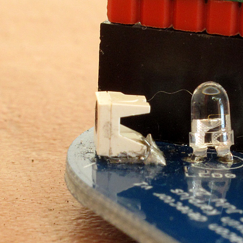
My first solder joint for the SFH325FA phototransistor tilted the transistor substantially, because the solder underneath formed a wedge. I reworked it a couple of times and finally got something sort of acceptable.
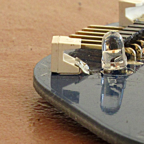
By the fifth phototransistor, I had worked out a technique that seemed to hold the phototransistor cleanly at a right angle. There is probably not much solder underneath the phototransistor, but the large wedge behind the phototransistor should provide sufficient mechanical strength.
Here are pictures of the populated board:
The back of the board does not look very different after being populated. I put one M3 screw in the bottom M3 screw hole, in order to see how compatible the screw hole design is with the screw head.
The top of the board, when populated shows how close channels 0 and 7 come to the Teensy board.
Here the board is on (powered through the USB cable), detecting an IR beacon about a meter away in the direction of channel 4. The green LED by the channel indicates the direction, and the green RGB LED indicates a strong signal.
I put the header pins on the pullup resistors, so that I could record the signal seen by the analog-to-digital converters. Unfortunately, the signal is much noisier than I expected:
The large spikes are at 15kHz, and probably correspond to noise injected by the ADC sampling.
I turned off the beacon and looked just at the noise spikes, using the 10× probe on the oscilloscope to get better bandwidth. I sampled at 100MHz and averaged 1000 traces to get a clean view of the signal (the triggering was set far enough from the background level that only fairly large spikes were captured, but close enough that the 1000 frames were gathered as quickly as possible).
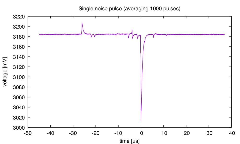
The pulses are very short (2–3 µs), so almost certainly correspond to the charging of the sampling capacitor. After looking at this waveform, I changed my sample time on the ADC to 2µs (it had been 1µs) to reduce the noise in what the ADC reports.
This post has gotten more than long enough, though I still have a couple of things that should be added: a schematic diagram of the board and a plot of the reported angle vs actual angle.
The schematics from Eagle are really ugly, so I’ve been thinking about redrawing them with SchemeIt—perhaps that can be a subsequent post.
The reported angle vs. actual angle plot is going to require building a jig that allow me to set the angle precisely. I tried jury-rigging something out of Lego today, but the result had too much slop—the board could not be reliably set level with the IR emitter at a fixed angle. The OED-EL-1L2 5mm IR emitter does fit in the middle hole of a Lego Technic brick, so I using Lego to align the IR emitter was attractive. I may have to make something out of wood and MDF (medium-density fiberboard) for a more solid test jig. The M3 screw holes will allow me to attach the board firmly to MDF with standoffs, and I can drill holes in Lego bricks to make a stand for the IR emitter.

")
 or hardback ($198)")

