Gas station without pumps

2015 September 2

Calibrating PteroDAQ frequency measurements

Filed under: Circuits course,Data acquisition — gasstationwithoutpumps @ 22:35
Tags: , , , ,

In PteroDAQ frequency channels, I wrote

One of the clocks is out of spec.  When the FG085 was putting out a nominal 500kHz signal, the PteroDAQ system measured it at 499958.5 Hz, which is –83ppm.  The two crystals should each be about ±20ppm, so an 83ppm discrepancy is larger than expected. With a nominal 5kHZ signal, the PteroDAQ system measured it at 4999.524 Hz (–95ppm).  I’ll have to take the function generator and PteroDAQ board into the circuits lab and use the frequency counters and function generators there to see what the actual accuracies are.  For anything that we do in the applied electronics class, 100ppm is good enough, but it would be nice to know how far off my instruments really are.

Today I took all three of my PteroDAQ boards (Teensy 3.1, Teensy LC, and FRDM-KL25Z) and my JYEtech FG085 function generator into the circuits lab, to compare the measurements made with the PteroDAQ to measurements made with the bench equipment in the lab.  I also used the function generator in the lab to get higher frequencies with less jitter, to see if that made a difference in the measurement.

The bench instruments I was using were

  • Agilent 34401A multimeter
  • Leader LDC822 frequency counter
  • Tektronix MSO 2024 digital storage oscilloscope
  • Agilent 33120A arbitrary function generator

Some  general observations:

  • The Agilent 33120A multimeter provided the highest precision on the measurements, but failed at 1MHz.
  • The multimeter also had some trouble with pulse trains with a lot of jitter, such as those produced by the FG085.
  • The oscilloscope routine reports the frequency for the inputs, but also has a “frequency” option on the measurement menu. The routine report seems to be stable and precise, while the “measurement” option fluctuated a lot—perhaps tracking the jitter in the signal.

The Leader frequency counter and the Agilent function generator agreed pretty well on frequencies, with the Leader counter reporting that the function generator was about 0.3–0.5ppm lower than it claimed to be.   The oscilloscope had less precision, and reported the Agilent function generator as 3–5ppm high.  The multimeter reported the function generator as 1.4–1.6ppm high.

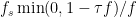
I’m interested in the PteroDAQ measurements relative to any of the bench instruments.  Here is a table of the ppm error for several frequencies (f_s is the sampling frequency for PteroDAQ looking at the frequency channel):

33120A setting Teensy 3.1 FRDM-KL25Z Teensy LC
MHz /33120A /Leader f_s /33120A /Leader f_s /33120A /Leader f_s
0.5 11.2 11.6 20 Hz  27.4 27.8 1 Hz  -24  -21.6 1 Hz
0.9 11.556 11.889 30 Hz  27.444  27.778 1 Hz  -23.889  -23.556 1 Hz
1.0 9. 9.3 31 Hz  27  27.5 1 Hz  -23.7  -23.5 1 Hz
2.0 -23. -22.5 62 Hz  26.5  27 2 Hz  -25  -25 2 Hz
3.0 -59.667 -59 100 Hz  25.333  26 3 Hz  -25.333  -25 3 Hz
3.9  24.359  24.872 4 Hz  -27.179  -26.923 4 Hz
4.0 -87.75 -87.25 125 Hz  -1660.8  -1660.3 4 Hz  -2059.5  -2059.3 4 Hz
4.5 -1777.555 -1774.667 140 Hz
avg -23.11 -22.66  26.339  26.825  -24.85  -23.263

The entries in red show the frequency counter failing by not counting all the edges—when the DMA channel can’t keep up, it silently ignores edges (not a great failure mode, since the numbers may look plausible while being several percent off). I did not include the red numbers in the average.

The KL25 and KL26 processors (FRDM-KL25Z and Teensy LC) both have fairly sharp transitions between counting every edge (at 3.9MHz) and missing many (at 4MHz). The K20 (Teensy 3.1) has stranger behavior, where it overestimates low frequencies and underestimates high frequencies.  There error a 3MHz is already fairly large.  I suspect that the problem may result from the shorter counter in the K20, which necessitated counting for shorter periods at high frequencies to avoid overflow.  There is a brief dead time at each period while the DMA counter is reset.

If there is a dead time of duration \tau, during which the first pulse is counted (captured by the port circuitry), but subsequent pulses in the dead time are missed, then the relative errors should be f_{s} \min(0, 1- \tau f) /f where f_{s} is the sampling frequency and f is the frequency being measured. Note that \tau f is an estimate of how many pulses arrive during one dead time.  If this is 1 or less, then no pulses are missed, otherwise only one of the arriving pulses is counted.

If the dead time for the Teensy 3.1 is about 900ns, then the errors should be about 0,0,0, -25, -57, and -81 for 0.5MHz, 0.9MHz, 1MHz, 2MHz, 3MHz, and 4MHz, consistent with the observed pattern.  With the longer counters  and so lower sampling frequencies on the other two boards, I expect errors of about 0,0,0,-1,-2,-3 ppm for a 1µs dead time, which is also consistent with the pattern of errors observed.

I could compensate for the error in PteroDAQ (on the host), by adding f_{s}\min(0, \tau f -1) to f.  The small initial error in f makes an insignificant change to \tau f. I will have to get a better estimate of the dead time than 900ns and 1µs, though, perhaps by counting instruction cycles for the compiled code between disabling and re-enabling the DMAMUX.  (Incidentally, do you have any idea how hard it is for a bioinformatician to type “DMA” instead of “DNA”?)

The ±27ppm error for the FRDM-KL25Z and Teensy LC boards seems fairly typical for a cheap crystal oscillator (which is usually ±30ppm).  Those errors are much larger than the <2ppm differences between the bench instruments, so it really doesn’t matter which of the bench instruments we treat as the “standard”.

What about the FG085 function generator? What is the ppm error on it?

FG085 setting 34401A
DMM
Leader LDC822
counter
30Hz  -23.667 to -121  0
3kHz  -88.333  -100
30kHz  -58.667  -63.333
327kHz  -55.352  -58.716
600kHz  -103.33  -58.500
999kHz  -58.158
avg  -76.4  -56.45

The multimeter had some difficult producing consistent reading when there was a lot of jitter in the signal. The frequency counter was more consistent, indicating that the JYEtech FG085 function generator was running about 57ppm slow, which is well outside the normal crystal frequency range. The cheapest crystals are ±30ppm, and ±20ppm often doesn’t cost any more. (There are ±50ppm crystals, but you have to go out of your way to find them, and they aren’t any cheaper.)

There are several possibilities:

  •  an error in the way the firmware for the FG085 sets up the frequencies,
  • I picked particularly bad frequencies to test at, or
  • the crystals are unusually bad.

The FG085 uses a 24-bit phase oscillator with a 2.5MHz clock (except for frequencies below 40Hz, where it uses a 10kHz clock), so the worst case rounding should be for 3kHz, with a phase increment of 20133 instead of 20132.659, making the frequency 17ppm too high.  If they truncated instead of rounding, then the frequency would be 32.7ppm low.  At 30kHz, truncation error would be only 3ppm, though, so this does not explain the consistently high errors.  I think that bad crystals are the simplest explanation—it is certainly consistent with the super-cheap (and bad) design of their DAC (see FG085 function generator bugs).

I’m a little disappointed with FG085 function generator, since for about 50¢ more, they could have made a much better instrument (using a resistor-ladder chip instead of discrete, unmatched resistors; using a ±20ppm crystal; drilling large enough holes in the top so that the buttons didn’t stick).

2015 August 28

DMA counter for event counting on Freescale Kinetis processors

Filed under: Circuits course,Data acquisition — gasstationwithoutpumps @ 18:25
Tags: , , , , , ,

The application note mentioned in PteroDAQ frequency channels is Freescale’s AN5083Using DMA for pulse counting on Kinetis, which I finally got around to looking up and reading today, after implementing frequency channels on the KL26, KL25, and K20 processors (Teensy LC, FRDM-KL25Z, and Teensy 3.1 boards, respectively).  The reason I looked it up finally was to look for a workaround for the biggest problem—namely that the CITER counter on the K20 has a maximum of 32767.  If I’m counting at the highest frequency (supposedly 8MHz or 6.26MHz, depending which documentation I believe, but I’ve not been able to get measurements much above 4MHz), that requires sampling at 125–245Hz or faster. But I often want to sample at factors of 60Hz, to alias out any frequency modulation from line interference.  The cruder DMA systems of the KL25 and KL26 use a 20-bit counter, and should be able to count to 4-5MHz (though they are likely to top out at 3MHz), so I could sample as slowly as once every 3.8s, even at the highest measurable input frequency.

I had no problem getting the counting to work with the 15-bit DMA_TCD_CITER counter. I can live with the 32767 count limit (at 60Hz sampling, that would be a 1.966MHz limit on the counting), but I wanted to see if I could use the optional interrupt that can be set up when the CITER counter ends to increment a software counter and reset the DMA counting.  That should give me an arbitrarily wide counter, at the cost of perhaps missing a count at the wraparound (an error of 30.5ppm, about the same as the clock error).

Unfortunately, AN5083 merely explains what I had already figured out for myself—without even the essential warning that you need a NOP after disabling the DMAMUX before looking at the counter to avoid a race condition on the KL25 and KL26:

    (&DMAMUX0_CHCFG0)[0] &= ~(DMAMUX_ENABLE);       // turn off at DMAMUX
    __asm__ volatile( "nop" );
    uint32_t count = 0xfffff - (DMA_DSR_BCR0 & 0xfffff);

They only say

The major loop counter of the DMA register DMA_TCDn_CITER_ELINKNO is limited to 15 bits, in the case where the channel linking feature of the DMA is not in use (refer to DMA chapter in the Reference Manual). Therefore, there is a limitation of 32K major loops count. So, user must check CITER register and make sure it will not reach to zero. If, CITER reaches zero, BITER will reload the value from BITER register.

I tried for a good chunk of yesterday to get the code working with the interrupt.  I can get the interrupt to occur (detected by turning off an LED in the interrupt return), I can read the longer frequency counter (detected by turning off an LED if the count to return is >32767), and the count is returned to be pushed on the queue, but something gets wedged and that longer count is never output to the host.

The processor needs to be power-cycled, the same as if the processor had gone into an infinite loop (which is what the Teensyduino unimplemented_isr routine does). I did disable the DMA error interrupt routine (with DMA_CEEI), so that isn’t the problem.  I even confirmed this by enabling the error interrupt and providing a dma_error_isr routine that turns off the LED, but the LED did not turn off.  I also checked the DMA_ES register at the beginning and end of the dma_ch0_isr routine and in the routine that reads the counter, and DMA_ES was always 0.  So if there is an error, it is not being reported by the hardware.

I suppose that an SWD debugging interface (not available on the Teensy 3.1 board) might be useful here, as I could at least check my conjecture that the processor is looping in the fault_isr routine.  It may be wedged somewhere else.  And there is always the possibility that there is an undocumented hardware bug (like the race condition between DMAMUX disabling and reading DMA_DSR_BCR on the KL26) that requires some workaround that I haven’t thought of yet.

I’ve given up on the higher resolution counters for Teensy 3.1 for now and just pushed the 15-bit implementation (with the interrupt code mostly commented out) to the BitBucket PteroDAQ repository.  If anyone reading this blog is familiar with the DMA interrupts on the K20 processor, please look at the code in kinetis_frequency.c and tell me what I’m doing wrong!

2015 August 25

PteroDAQ frequency channels on FRDM-KL25Z

Filed under: Circuits course,Data acquisition — gasstationwithoutpumps @ 23:53
Tags: , , , , ,

In PteroDAQ frequency channels I said

The next step for me is to implement frequency channels for the FRDM-KL25Z board (pretty much identical to the KL26 on the Teensy LC, except for having to use the MBED syntax for the register setting rather than the one Teensyduino uses) and the Teensy 3.1 board (the K20 DMA is much more complicated, so it will probably take me a while to figure out and set up—especially if it also has undocumented race conditions). Once I get those working, I’ll have to figure out how to do the GUI so that people can quickly figure out that which combinations of frequency channels are legal. I’ll probably want to do that with separators in a menu, greying out sections that already have frequency channels in use.

I got about half of that done today.  I started out with how to grey out the frequency channels that were inaccessible (because another pin on that port was being used)—but doing that lead me to needing to list all the current channels, which was done in several different places already and was rather awkward.  From there I decided to clean up and refactor a lot of the GUI code, which had gotten rather long and confusing.

So most of the day was spent on refactoring the GUI, breaking it up into classes and getting rid of global variables.  I think that the GUI code is more maintainable  now, but there are still a few things that feel like they are in the wrong place in the code, so some stuff may move around a little in future releases.

After the refactoring, greying out the unavailable frequency pins was pretty easy, and I’m reasonably happy with the user interface for pin selection now, though I think I need a new icon for frequency measurement.  I have a period of a sine wave for analog channels, and a period of a square wave for digital channels, but I don’t have as obvious an icon for frequency channels.  (I was considering just a big “Hz”, but that would not look compatible with the sine and square wave icons.)

Adding frequency channels for the FRDM KL25Z board did not take long—the biggest trouble was converting the KL26 code for the Teensy LC into MBED’s format for accessing registers.  Just about everything else is the same (except that the KL25 has only 2 ports that can control the DMA counters: A and D, rather than the 3 (A, C, and D) of the KL26. I have pushed the code for the frequency channels up to the PteroDAQ site on BitBucket.

I don’t know whether I’ll get the Teensy 3.1 code done tomorrow—I have to go into the office for office hours and for the banana slug genomics meeting, and I need to start working on my biobibliography and teaching/research statements for my merit review.  They are due early in September, and I’ve not started on them yet.

I hope to have the frequency channels working on the Teensy 3.1 by the end of the week, so that I can rewrite the chapter of my book on the hysteresis oscillator, to use the frequency channels, rather than a separate frequency detecting program as I used for the last couple of years.

2015 August 24

PteroDAQ frequency channels

I’ve been trying to add frequency channels to PteroDAQ, so that it can plot the frequency of an input on a digital channel.  So far, I’ve only implemented this for the Teensy LC, which uses a KL26 ARM processor.  Because I want to be able to mix frequency channels with regular analog or digital channels, I’m using the method that counts rising edges in a fixed time period (the sampling period set for PteroDAQ), rather than timing how long there is between edges.  The chosen edge-counting method is more appropriate for high-frequency signals than for low-frequency ones, but by using long-term averaging, one can measure fairly low frequencies also.

In order to count adequately high frequencies, I need to run a hardware clock that does not use interrupts to do individual counts, but which can keep counting why the processor does useful stuff.  One choice (made, for example in the Teensy FreqCount library) is to use the low-power timer LPTMR.  But only one pin on the Teensy LC can be used with this timer—pin 13, which is also the LED output pin.  I wanted something more versatile, that could be used with any digital pin and that could have multiple frequencies being counted at once.

The closest I’ve been able to come so far is to use the DMA channels as counters (a suggestion my son made to me, based on ideas he saw in a Freescale application note).  I can use any pin on Port A, C, or D to control a DMA channel, and there are 4 DMA channels, but each port only provides one signal to the DMA, so I can have 3 independent frequency measurements (one for any pin from Port A, one for any pin from Port C, one for any pin from Port D).  If I use the same trick on the Teensy 3.1, which is a K20 processor, I can have 5 independent measurements, one each from Ports A, B, C, D, and E.  On the FRDM-KL25Z board, I only get 2 measurements, one each from Ports A and D.

To use the DMA channel as a counter, I had to set it up with a large byte count (the max is 0xFFFFF, or 1,048,575) and have the DMA do a no-op 1-byte transfer from a fixed source to a fixed destination on each external signal. On each read of the frequency, I read the remaining count and subtracted from 0xFFFFF to see how many external signals had happened, and put that count in the queue for sending to the host computer like any analog read.

It took me a long time to get the code working on the Teensy LC (about 2 days).  The first problem was just understanding all the pieces of the DMA system:

  • Using the SIM_SCGC6 and SIM_SCGC7 registers to turn on clocking to the DMAMUX and DMA
  • Using DMAMUX0_CHCFGn to route signals from the ports to the DMA channels
  • Setting up the PORTx_PCRn register to send DMA signals on rising edges
  • Setting up the DMA_SAR, DMA_DAR, DMA_DSR_BCR, and DMA_DCR registers for the DMA operation itself.

Another big chunk of time was spent rearranging some of the python software, so that the frequency channels could be selected in the GUI and the communications protocol to the microcontroller board updated to handle frequency channels.

But the biggest chunk of time was spent trying to debug a race condition.  No matter what I did, running a high-frequency signal with a high sampling rate resulted in things failing in unpredictable ways after an unpredictable delay (the counts all coming out 0, the communication packets getting incorrect checksums, or just freezing).  I had to power cycle the Teensy LC after each failure to try again.

I tried all sorts of debugging tricks (no SWD debugging interface on the Teensy LC), including sending contents of the various DMA registers instead of the count, to see which things were going wrong.  Unfortunately, almost everything seemed ok until it failed, and then nothing came out.  I was convinced it was a race condition—but where?

I tried various ways of turning the counting on and off, based on different suggestions in different Freescale manuals (using the ERQ bit in DMA_DCR or using the ENABLE bit in DMAMUX).  I even tried various combinations of the turning on and turning off in different orders.  It was clear to me that the problem was in reading or resetting the DMA_DSR_BCR register, but there were several places where a race might be occurring and no help in any of the reference manuals.

By trial and error, I finally figured out that if I used the DMAMUX enable bit to turn off the counting, and put a NOP after it before looking at the DMA_DSR_BCR register, the race condition went away.  The crucial problem seems to be that looking at DMA_DSR_BCR at the same time that hardware is trying to change it results in unpredictable behavior—not just unpredictable values for the read, but seriously wedging the DMA so that a hardware reset is needed.  The extra NOP makes sure that any pending DMA operations are completed before accessing the DMA_DSR_BCR register.  This warning does not seem to be present in any of the KL26 documentation—I’m not sure the engineers who designed the DMA were aware of it.  Either that or the engineers failed to communicate the importance of this constraint to the tech writers who did a sloppy cut-and-paste job in writing the KL26 DMA documentation (for example, there are references to a non-existent “TCDn”, by which they mean the 4 registers DMA_SARn, DMA_DARn, DMA_DSR_BCRn, and DMA_DCRn).

Running the frequency channel with a square-wave input from the FG085 function generator lead to some more discoveries:

  • The samples taken by PteroDAQ have a fairly large amount of jitter at high sampling frequencies.  At 10kHz sampling and a 500kHz input, the number of observed edges varied from about 47 to 53, representing a ±6µs variation on the nominal 100µs.  My son suggested that the jitter was caused by the USB communications—if the timer interrupt occurred while the USB interrupt was in progress, the sample would be delayed up to about 6µs, and this could happen about every millisecond with heavy communication. Sure enough, the long periods were followed immediately by short periods, and some clusters about 1msec apart occurred (though not ever millisecond).  At low sampling frequencies, there is less USB communication, so a lower probability of getting the 6µs delay, which also represents a much small fraction of the period, so I did not see jitter at lower sampling frequencies.
  • One of the clocks is out of spec.  When the FG085 was putting out a nominal 500kHz signal, the PteroDAQ system measured it at 499958.5 Hz, which is –83ppm.  The two crystals should each be about ±20ppm, so an 83ppm discrepancy is larger than expected. With a nominal 5kHZ signal, the PteroDAQ system measured it at 4999.524 Hz (–95ppm).  I’ll have to take the function generator and PteroDAQ board into the circuits lab and use the frequency counters and function generators there to see what the actual accuracies are.  For anything that we do in the applied electronics class, 100ppm is good enough, but it would be nice to know how far off my instruments really are.
  • The FG085 glitches (turning off the output for a while) when changing frequency.  I plotted the frequency as I stepped the frequency down in 100Hz steps from 5kHz to 2kHz:
Each time I turned the knob, the FG085 turned off the output for a while, resulting in a large number of missing counts.

Each time I turned the knob, the FG085 turned off the output for a while, resulting in a large number of missing counts.

The next step for me is to implement frequency channels for the FRDM-KL25Z board (pretty much identical to the KL26 on the Teensy LC, except for having to use the MBED syntax for the register setting rather than the one Teensyduino uses) and the Teensy 3.1 board (the K20 DMA is much more complicated, so it will probably take me a while to figure out and set up—especially if it also has undocumented race conditions). Once I get those working, I’ll have to figure out how to do the GUI so that people can quickly figure out that which combinations of frequency channels are legal. I’ll probably want to do that with separators in a menu, greying out sections that already have frequency channels in use.

Once all that is done (later this week??), I’ll push it up to the PteroDAQ repository.

2015 August 16

Arduino-compatible software for FRDM-KL25Z board

Filed under: Circuits course — gasstationwithoutpumps @ 10:13
Tags: , , , ,

As many of you have realized, I’m finding that doing multiple-platform support for the PteroDAQ system is a bit annoying.  One irritation is that the mbed.org compiler for the FRDM-KL25Z board is not integrated with the other compilers—not even sharing the same file system.  So every time I make a change, I need to transfer all the files between my laptop and the mbed website—I can’t use mercurial or git to keep things in sync.

All the other boards I’m using can be compiled for locally and downloaded to with the Arduino IDE.  It is not a particularly powerful IDE, but it is dead simple to use, and it runs on my old Mac OS 10.6.8 (at least, if I use Arduino 1.0.6—the newer versions seem to assume new Macs).  A lot of the “professional” IDEs assume that you replace your computer every year and have the latest OS installed, or that you use nothing but Windows.

Since the FRDM KL25Z board is currently one of the best price/feature microcontroller boards on the market, I figured that someone must be working on an Arduino plug-in for the hobbyist market.  So I did some Google searches and found something that initially looked promising: Arduino-compatible software library for FRDM-KL25Z board – CodeProject.

FRDM-KL25Z is an interesting ultra low cost board with 32-bit microcontroller. What makes it interesting for the Do-It-Yourself community is low price (about $13) and also the compatibility with the Arduino pinout. If you are Arduino user like me, you will probably also feel interest if you hear about a board which could, for less than half the price of standard Arduino board, give you a 32-bit ARM MCU running at 48 MHz with 128 KB of FLASH and 16 KB of RAM memory, on-board accelerometer and more. But as you might have expected, there is a “catch”. The  FRDM board has the same layout of pins, so you can connect the Arduino shields to it, but there is no software compatibility. You cannot use the Arduino API functions such as digitalRead, delay, etc. and you cannot program the board from the Arduino IDE. I was thinking it would be nice if you could… And this article is my first step in this direction.

Digging deeper, though, disappointed me.  They are trying to provide the trivial parts of the Arduino API, but they do their compiling with Kinetis Design Studio (which doesn’t run on Mac OS 10.6.8, and which is supposedly a bit of a bear to learn to use).  I’m more interested in the opposite combination—using the Arduino IDE, with only minimal use of the Arduino API (which I find a bit too inefficient for my tastes), except for a couple of difficult things (like the USB stack).

They’ve also licensed their code with a contagious LGPL license, which is too restrictive for the PteroDAQ code.

What I’m looking for is something like the Teensyduino implementation, but for the FRDM KL25Z board. I’ll have to look at how the Teensy loader is integrated into the Arduino IDE—if I can figure out how to put in copying a .bin or .s19 file to an emulated flash drive instead, then I can probably program for the KL26Z board, and possibly for the KL25Z board.

Next Page »