Last night I fit a simple thermal model to temperature measurements of some power resistors: 
I ran into problems with the 1.8Ω 50W THS501R8J resistor, because it heated up very fast and I could only get a few measurements when delivering power, before I had to turn it off. I proposed adding a heatsink, a 6″×12″ sheet of aluminum 0.063″ thick, to increase the thermal mass M and decrease the thermal resistance D. I estimated that the thermal mass should increase by the heat capacity of that much aluminum (74.33 cm3 at 2.422 J/°K/cm3, giving 180 J/°K), but I did not have a good way to estimate the change in thermal resistance.

The 6″×12″ plate is much larger than the power resistor, which is bolted in the center with M3 screws (American 6-32 screws are a little too big for the holes in the resistor). I used a thin layer of white thermal grease to get better thermal conduction between the resistor case and the aluminum plate.
I do not expect the simple thermal model to work well, because it assumes that you have an isothermal object—all the aluminum at the same temperature. But a large flat plate is going to have significant thermal spreading resistance, so that the resistor in the center is hotter than the edges of the plate.
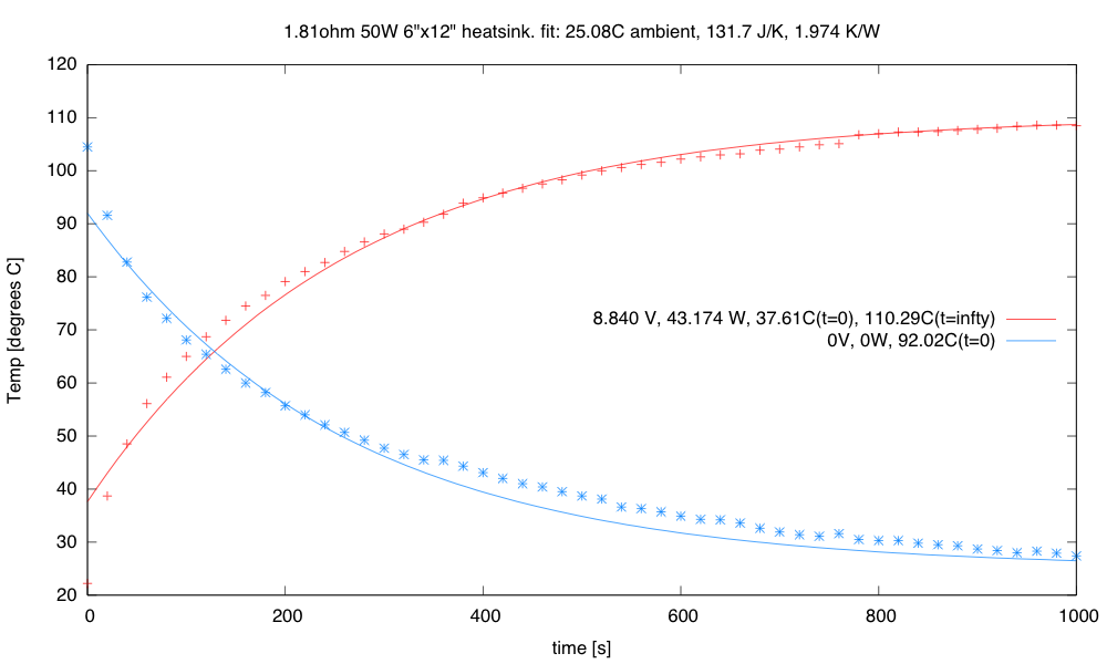
With a heatsink the time constant DM is about 260s, only a little faster than the 347s without the heatsink, but the thermal resistance is much lower, so the maximum temperature (PD+A) is much lower.
As expected, the fit is not great. When cooling off, the initial temperature of the resistor is higher than of the surrounding plate, so the initial cooling at the resistor is faster than the eventual cooling, when resistor and the plate are closer in temperature, because heat is being transferred to the plate as well as to the air. The increase in thermal mass (about 100 J/°K) was less than my crude estimate based on the heat capacity of the added aluminum (180 J/°K)—this is probably also due to the thermal spreading resistance and the non-uniform temperature of the heatsink.
| resistance | rated power | heatsink? | test power | M [J/°K] | D [°K/W] | DM [s] | T∞ [°C] |
|---|---|---|---|---|---|---|---|
| 10.10Ω | 100W | No | 8.288W | 101.7 | 6.38 | 649 | 75.7 |
| 8.21Ω | 50W | No | 10.169W | 32 | 11.58 | 371 | 143.7 |
| 1.81Ω | 50W | No | 43.174W | 31.9 | 10.87 | 347 | 495.8 |
| 1.81Ω | 50W | Yes | 43.174W | 131.7 | 1.97 | 260 | 110.3 |
Note: the asymptotic temperature T∞ in the table above is with the 9V power supply I have, which does not have quite constant voltage over the range of powers tested. With a 12v supply, temperatures would be much higher: 
I should probably test the 10Ω 100W resistor on the heatsink also, to see if that reduces the time constant DM. I expect the thermal mass to go up by something between 100 and 180 J/°K, but the thermal resistance to drop to around 1–1.5 °K/W, getting DM in the ballpark of 300s. I don’t think I’ll do that today, though, as making measurements every 20 seconds for 2000 seconds is tedious and leads to cramping in the hand that aims the IR thermometer and keeps the trigger pulled.
Which raises a pedagogical question: Should I have students do the measurements? Should I show them how to make a recording thermometer with a thermistor first? They’ll need to figure out how to use a thermistor for measuring air temperature anyway.
The thermistors I have at home (NTCLE100E3103JB0) only go up to 125°C, and I’d want them to have one that goes to at least 175°C for this lab, which means using something like NTCLG100E2103JB (10kΩ, ±5%, ±1.3% on B-value, -40°C to 200°C), which is only 35¢ in 10s, so still cheap. I should get myself some of these higher temperature thermistors and test out the recording . (Or the tighter tolerance NTCLE203E3103SB0, which only goes up to 150°C, or the wider temperature range 135-103LAF-J01, which goes to 300°C.)
How will I attach the thermistor to the resistor for temperature measurement? tape? (I have to be sure not to short out the thermistor leads on the aluminum case of the resistor.)
Air temperature sensing poses less of a mounting challenge, but the thermal delays will be quite large—I have to look at how difficult it will be to tune a PID or PI controller with large delays—we really don’t want huge overshoot. If the students have multiple temperature measurements (resistor temperature and air temperature, for example), they may need a more complicated control loop than a simple 1-variable PID controller. How much can we simplify this? (Perhaps a PI or PID controller based on the air temperature, with over-temperature shutdown on the resistor temperature? Then tuning the PID controller with the constraint that the gain be kept low enough to keep the over-temperature shutdown from kicking in?)

")
 or hardback ($198)")


[…] that I have a power resistor and heatsink, and have verified that my power supply is capable of delivering 50W, I can try making a thermal […]
Pingback by PWM heater and fan | Gas station without pumps — 2014 September 14 @ 00:18 |
[…] about the eventual PWM value for resetting the cumulative error on a setpoint change. I have a model for the resistor temperature in still air, but the fan makes a huge difference, both in the thermal resistance (and so both the […]
Pingback by Controlling the heater and fan | Gas station without pumps — 2014 September 15 @ 18:03 |
[…] Thermal models for power resistor with heatsink applies the simple thermal model to a power resistor with a heatsink, where it does not fit quite as well. […]
Pingback by Putting the heater in a box | Gas station without pumps — 2014 September 17 @ 21:04 |
[…] design seminar, PWM for incubator, More on incubator design, Thermal models for power resistors, Thermal models for power resistor with heatsink, PWM heater and fan, PWM heater and fan continued, Controlling the heater and fan, Putting the […]
Pingback by More on freshman design projects | Gas station without pumps — 2015 January 19 @ 22:01 |