Classes start tomorrow, so I spent yesterday making sure that the incubator control project was feasible. I had gotten the fan feedback control working well back in September, but I’d put the project aside for Fall quarter and only got back to it this week. As a reminder, here are the previous posts on the project:
- Temperature-control project for freshman design seminar describes an idea for a possible project for the freshman design seminar.
- PWM for incubator gives a bit more detail on the temperature-control project.
- More on incubator design continues the incubator design.
- Thermal models for power resistors presents thermal models for 3 power resistors without heatsinks.
- Thermal models for power resistor with heatsink applies the simple thermal model to a power resistor with a heatsink, where it does not fit quite as well.
- PWM heater and fan talks about doing PWM for a fan and for a resistor as heater.
- PWM heater and fan continued continues the previous design work, reducing the electrical noise and making PI control loops for the fan and the heater.
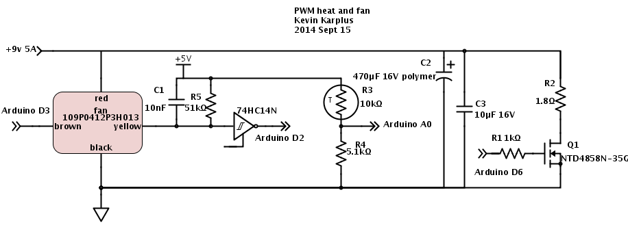
- Controlling the heater and fan talks about progress on the control loops and gives the schematic for the circuit discussed in the two previous posts.
- Putting the heater in a box shows the physical layout of the partially completed incubator and discusses the (meager) progress today.
- Improving feedback for fan shows the working control loops, and compares on/off, hysteresis, PI, and PI with anti-windup.
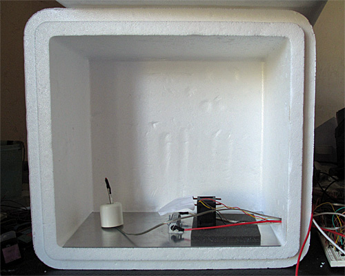
Here is the interior of the styrofoam box, with the lid open. The 6″×12″ aluminum plate covers the bottom. The thermistor is on the left, propped up by a rubber foot, the resistor in is the center, and the fan is sitting on a foam pad on the right. (The foam is to reduce noise until I can get the fan proper mounted in a baffle.)
I left the foam out this time, which made for a somewhat noisy fan, and I still haven’t built a baffle—I’m still using the bent-wire-and-paper deflector shown in the photo. What I worked on yesterday was the software—since the temperature changes are fairly slow, it takes a long time to tune the control loops.
One thing I did was to try to reduce measurement noise further on the thermistor measurements. I now add 60 analog-to-digital readings. They’re 10 bits on the Arduino-compatible board (a Sparkfun redboard), so adding 60 still fits in an unsigned 16-bit word. I now get noise of about ±0.05°C, which is half the least-significant-bit of the converter. I doubt that I can do better in precision without switching to a processor with a better analog-to-digital converter, though I could do digital filtering with a 1Hz low-pass filter to smooth out the remaining noise.
I copied the fan feedback control loop (with the anti-windup provisions) described in Improving feedback for fan for temperature control, but made two changes:
- I changed the integration time and K_p for the thermal control loop, since the temperature response is much slower than the fan response.
- Because of the huge asymmetry in the temperature response (the resistor and metal plate can heat up much more quickly than they cool down), I turn off the heater the moment it gets over temperature, no matter with the PI loop suggests, but I only switch to full-on when the air temperature is 3°C too cold. For the fan, I used a symmetric window around the set point for using the PI loop rather than full-on/full-off.
Here are some results from tuning experiments:
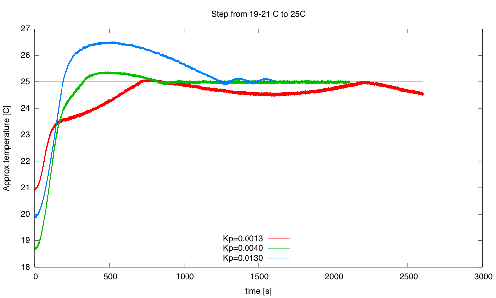
The blue curve switched to PI control at 23.5°C, the other two at 22°C. The green curve has pretty tight control over the temperature, but does overshoot a bit.
The initial temperatures were not all identical, because I wasn’t always willing to let everything cool down all the way to room temperature after each tuning run. I could only do about 1 tuning run an hour, which could pose problems for the freshman design seminar, as we don’t have long lab times—only the 70-minute lecture-schedule meeting times.
I continued the best of those runs with another step, up to 35°C, then let it cool down.
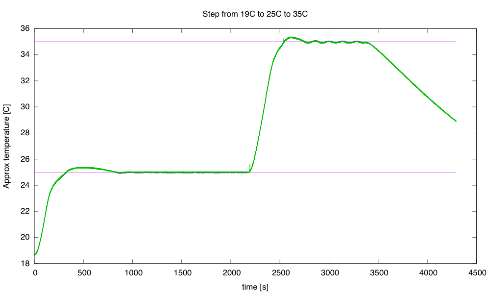
The step to 35°C has more ringing than the step to 25°C. I terminated the run before it had finished cooling, because the 32-bit µs timer wrapped around.
The cool-down at the end fits a 0.0069 °C/s line better than it fits an exponential decay to the ambient temperature. If I do fit an exponential decay curve, I get a time constant of around 1975 seconds.
A simple thermal-resistance, thermal-capacity model is not a very good one for predicting how the system will behave, particularly since we’re not measuring the temperature of the large thermal mass (the aluminum plate and power resistor), but of the air, which has a large thermal resistance from the plate. The time constant for the aluminum-air transfer is larger than the time constant for the electricity-aluminum transfer, which is why we get so much overshoot when we turn off the power to the resistor—the aluminum plate has gotten much hotter than the air, and continues to transfer heat to it, even though no more heat is being added to the aluminum.
Still, it is worth seeing what we get if we model the box a simple thermal mass and thermal resistor. The steady-state 35°C seems to need about 9W (PWM of 51/256) and the 25°C 3W (PWM of 17/256) with an ambient temperature of about 19°C, implying that the styrofoam box has a thermal resistance of about 1.9°C/W.
To see what is really going on, I’ll have to heat the box to 35°C, then start the cool down with a reset 32-bit timer.
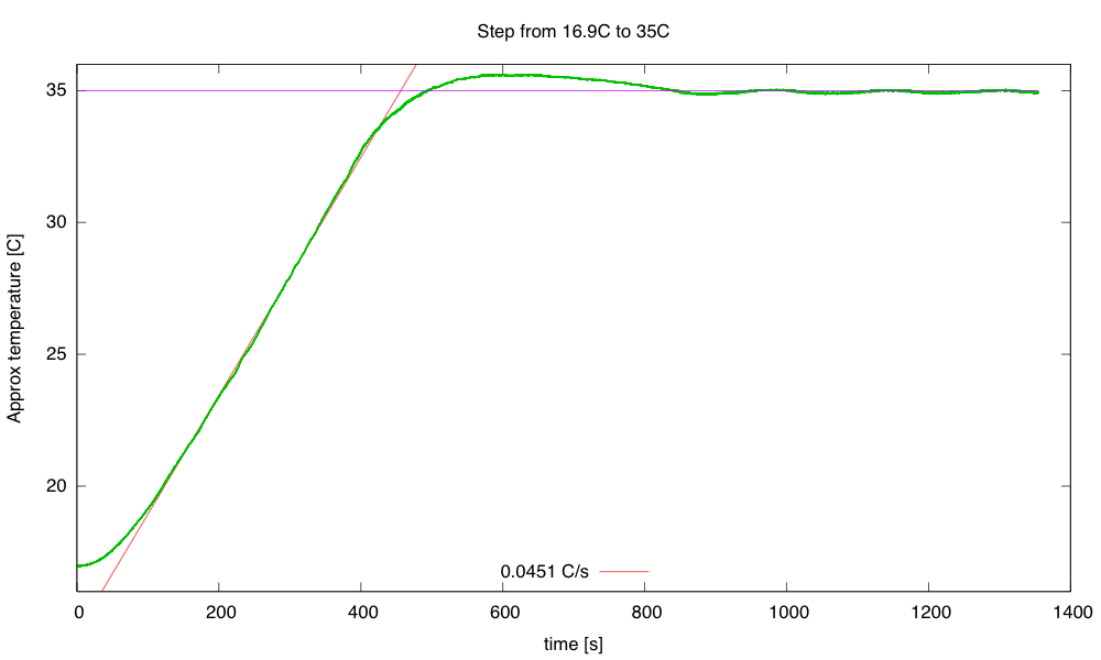
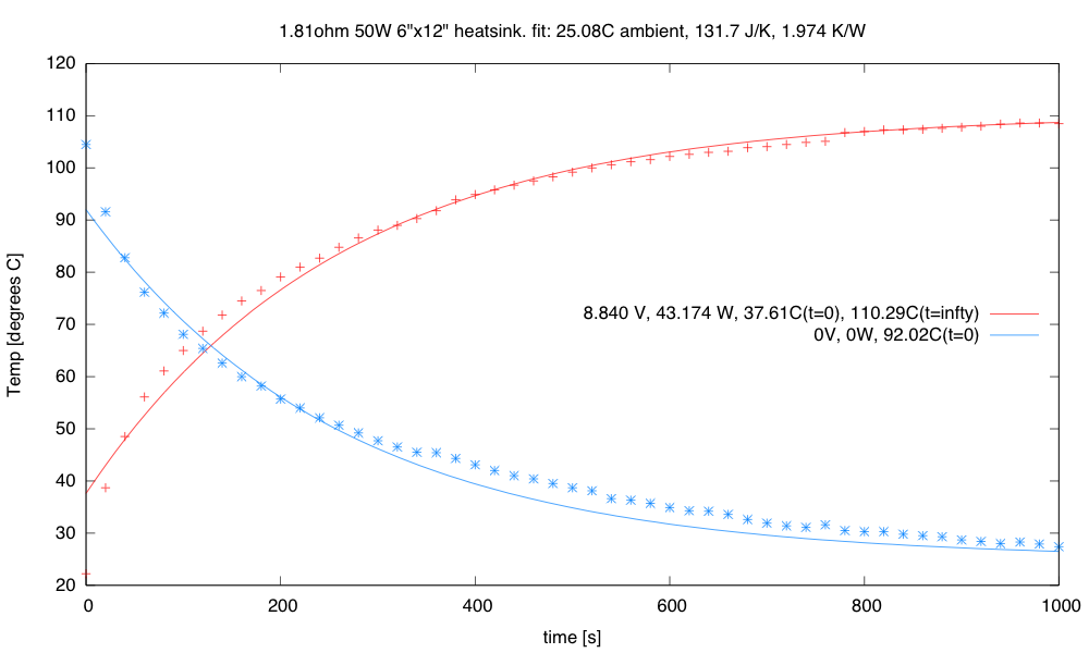
Single-step warming from 16.9°C to 35°C. The steady state at 35°C is about 9.32W, for a thermal resistance of 1.8°C/W. The rise of 0.0451°C/s at 45W implies a thermal capacity of 998 J/°C.
Heating at 45W (9V, 1.8Ω) results in a temperature rise of about 0.0451 °C/s. This warm-up rate at 45W implies a thermal capacity of about 998 J/°C. We may want to adjust our thermal capacity estimate, since some of the 45W put in escapes through the box—maybe about 3–4W at the temperatures where the rise was measured. This reduces the thermal capacity estimate to about 910 J/°C.
The cool down from 35°C starts out as a straight line (about -0.0074°C/s or -26.5°C/hour), but gradually starts behaving more like the exponential we would expect from a thermal-resistance and thermal-capacity model.
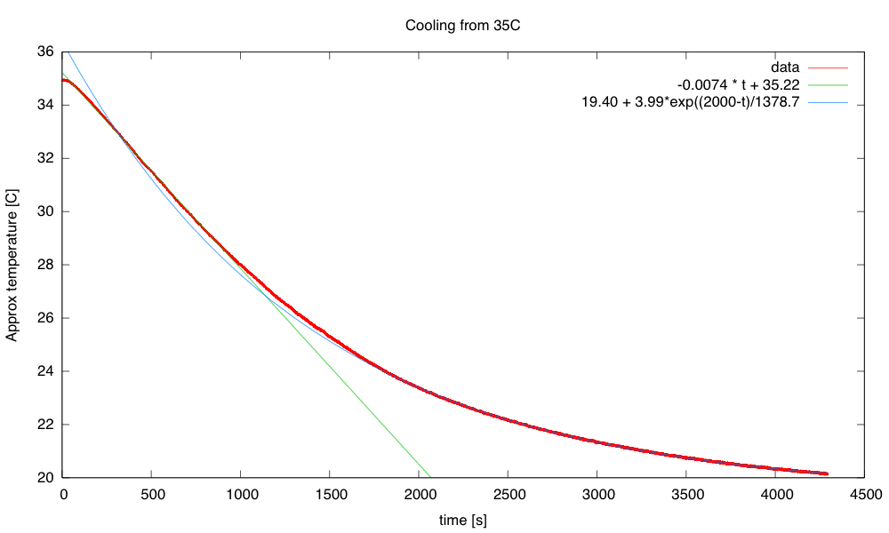
The time constant for the cooling is about 1380s, but the initial cooling is too slow for a simple exponential.
The time constant of 1380 s, combined with a thermal capacity of 910 J/°C gives a thermal resistance of 1.5 °C/W, a bit lower than the 1.8°C/W I estimated from the steady-state power.
I continued the cooling (with the timer wrapped around) to see if I got a clean exponential at low temperature differences:
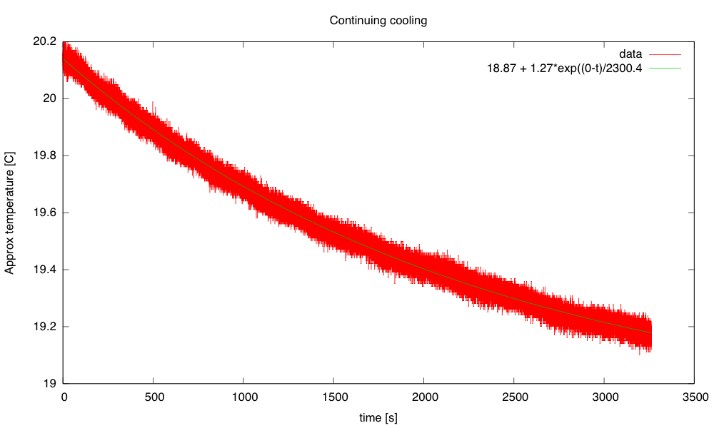
The exponential seems to fit well here, with a time constant of 2300s. Combined with the 910 J/°C, this gives a thermal resistance of 2.5°C/W, which seems a little high compared to the other estimates.
So I’ve made some progress on the thermal control loop (though I’d like to reduce the overshoot and ringing) and I have a crude model for the box: a thermal mass with capacity about 910 J/°C and thermal resistance 2±0.5 °C/W.
Still on my to-do list for this project:
- Consider using a PID controller for the temperature to get faster response without overshoot. (If I can reduce the noise problem.) I should be able to reduce the noise with a digital filter, but I’m already pushing well beyond what I’m comfortable covering in a freshman class. Tuning a PID controller is even trickier than tuning a PI controller, which is already going to take most of the quarter to teach.
- Design and build baffling for the fan to get better airflow in the box. This might be a good thing to get students to do, particularly if we can get them to learn how to use the laser cutter. But even handsaws would suffice, given some thin plywood or masonite, some angle irons, and nuts and screws.
- Figure out how to get students to come up with workable designs, when they are starting from knowing nothing. I don’t want to give them my designs, but I want to help them find doable subproblems. Some of the subproblems they come up with may be well beyond the skills that they can pick up in the time frame of the course. The more I work on this project, the more I realize that I and the students will have to be happy with them having explored the options, without getting all the problems solved.
- Add changes to the cumulative error term whenever KP or TI are changed, to keep the PWM output the same after the changes—currently changing any of the control loop parameters adds a huge disturbance to the system. I don’t know how important this is—I’ve been doing my tuning of the thermal loop by recompiling, rather than by changing parameters on the fly. The quick changes were handy for the fan loop, where I could see things happening quickly, but for the thermal loop each experiment took about an hour, so there was no need for a fast parameter change.
- Research control algorithms other than PI and PID, particularly for asymmetric systems like the temperature control, where I can get fairly quick response to the inputs when heating, but very slow response when cooling. The asymmetric window for switching between on/off and PI control seems to have helped here, but there is probably a more principled way to handle asymmetric control inputs. Maybe I should ask some of the control-theory faculty for some pointers.
- Develop a more detailed thermal model with separate components for the aluminum plate and the air in the box. It may be worth adding another thermistor, taped to the aluminum plate, to monitor that temperature. The extra thermistor would also allow much tighter temperature control, avoiding overshoot on air temperature.
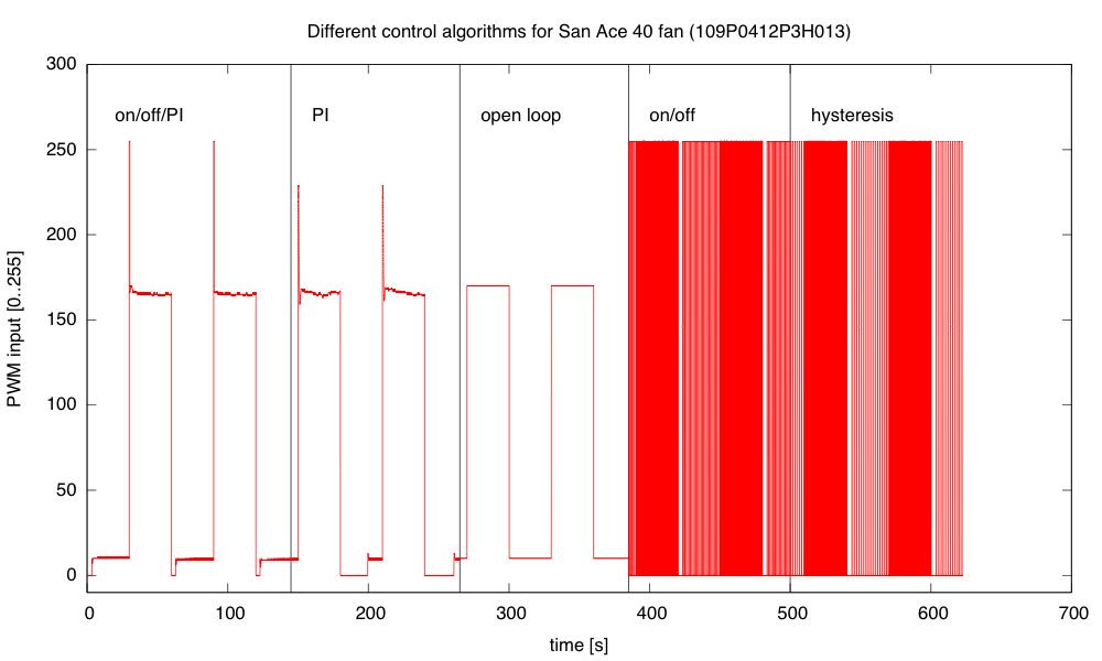
![The mixed algorithm does a very good job of control, with little overshoot. The simple PI algorithm has substantial overshoot, particularly when the control loop wants a PWM value outside the range [0,255]. Open loop has significant offset and wanders a bit. On/off control oscillates at about 10hz, and adding hysteresis makes the oscillation larger but slower (about 5Hz).](https://gasstationwithoutpumps.files.wordpress.com/2014/09/fan_multiple.png)
 , where P is the power in watts, D is thermal resistance in °K/W, M is thermal mass in J/°K, A is the ambient temperature in °C, and T0 is the initial temperature.
 . The asymptotic temperature is also the maximum when the resistor is sitting in still air that is unconfined. A fan would reduce thermal resistance and make the asymptotic temperature lower, but confining the resistor in a box (like in the incubator design) would make the “ambient” temperature not be constant—the relevant thermal resistance is how slowly the air in the box loses heat, which for the thick-walled styrofoam boxes we’ll use is a very high thermal resistance. Without a feedback loop and PWM to keep the power down, even the 10Ω resistor would get very hot in a styrofoam box.
")
 or hardback ($198)")

