I mentioned in LED lighting for bathroom that the LED strips I had bought from China were much yellower than I expected and were lower-powered than the seller claimed. I believe that they sent me a different LED strip than what they had advertised (a cheaper product using 3030 LEDs instead of 5050 LEDs), but that is a risk one takes in ordering through AliExpress. Although I could have started a claim against the seller, I had already cut up and installed the strips, so I did not feel justified in asking for a refund. The amount was small enough that I just wrote it off and ordered another set of LED strips through AliExpress, making sure they were from a different seller and were well described on the web page.
The new strips did indeed use the 5050 SMD LEDs that both strips claimed to use—the LEDs were substantially larger, through the strips were the same size. I installed the new strips alongside the old ones, and they are substantially brighter and whiter. It is also clear that the old power supply I was using was not able to handle the load of the new strips, reaching a current limit of about 1.5A with voltage dropped to about 11V (though it claimed to be 12V 2A). I have ordered a new 12V power supply, Mean Well SGA60U12-P1J, which is a modern, efficient power supply and should be able to deliver 5A. Will that be enough?
Because my old supply was being limited by the current it could supply, I did not have a good estimate of the power needed by either the new or old strips. In both cases, the seller had said 14.4W/m, which is 1.2A/m @ 12V. I know that spec is wrong for yellowish lights (they are smaller LEDs than the 5050 LEDs I’d ordered), but I was curious what the power consumption really was.
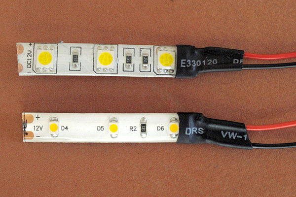
So I decided to measure a 5cm length of each of the strips (5cm is the smallest unit for the strips, standard for most LED strips). The 5050 strip has 3 resistors in each unit, so consists of 3 copies of a 150Ω resistor in series with an LED module that internally has 3 LEDs in series. The yellowish strip has only one resistor in a 5cm segment, so consists of three LEDs in series with a 100Ω resistor. I can tell the resistor values, because they are clearly labeled SMD parts.
To make the test pieces, I cut the strips at the 5cm cut line, then used a razor knife and a pair of long-nose pliers to peel away the waterproofing from the copper pads. I soldered red and black stranded wires onto the pads, then used some heat-shrink tubing to insulate and stabilize the connection, providing a tiny amount of strain relief.

The newer 5050 strip is on the top. The incorrectly shipped 3030 strip is on the bottom.
I wanted to make I-vs-V plots for the LED strips using PteroDAQ, but the Teensy board ADC is limited to 3.3V, and the voltages I needed could go well over 12V (12V for the LED strip plus whatever I needed for the current sensing). I could keep the voltage down for the current sensing by putting the current-sense resistor on the ground side of the LED strip. If the 14.4W/m @12V figure from the seller is accurate, then I’d expect about 60mA for a 5cm section, so a current-sense resistor <55Ω would keep the voltage in a measurable range. But to measure the voltage across the LED, I need a voltage divider.
My first attempt was to use a 62kΩ and a 15kΩ resistor to get a nominal divider ratio of 0.1948. To check this ratio, I used the function generator to sweep over most of the 3.3V range, measuring the input and output of the voltage divider at each point with two channels of PteroDAQ. I saw some weird non-linear behavior of the output of the voltage divider vs. the input, so I did a fit assuming that the ADC had a fixed offset voltage, besides the scaling of the voltage divider (this 2-parameter model worked better for tests that I’ll describe below than just a scaling by the voltage divider, so I used it for this initial test set also). Although I usually make PteroDAQ measurements in volts, I redid the measurements in raw ADC integer values, because the pattern of the values suggested a relationship to the binary encoding.

The error in the output voltage measurement shows a distinctive pattern, corresponding to the high-order bits of the ADC value.
These results were unexpected, so I decided to explore further, replacing the 62kΩ:15kΩ voltage divider with a 10kΩ potentiometer and using it at various settings. It was with this data that I decided that a constant offset was needed to get the voltage divider fits to work well:

With the 10kΩ potentiometer, the patterning of the errors is barely visible, and the errors are much smaller than with the 62kΩ:15kΩ voltage divider. The offset was chosen for the d=0.0581 divider, but worked well for all the dividers.
Given that the patterned errors were now much smaller than the random noise (which I had already minimized by using 32× hardware averaging), I suspected that the problem was not an inherent non-linearity of the ADC, but poor behavior of the ADC due to the high impedance of the source. I tested this two ways: first, by adding a resistor between the voltage divider output and the ADC pin (which should increase the source impedance without changing the voltage being measured) and second, by using a unity-gain buffer to provide a low-impedance source for the ADC pin.
With a 15kΩ resistor between the potentiometer voltage divider and the ADC input, I got patterned errors similar to what I first observed with the 62kΩ:15kΩ divider, but the offsets needed to get good fitting did vary a bit with the divider ratio:

The problems with the 62kΩ:15kΩ ADC measurements were caused by the high-source impedance, since adding extra impedance to the 10kΩ voltage divider created similar problems.
I also tried 62kΩ added between the voltage divider and the ADC pin, but that caused huge problems with reading the value.
Adding a unity-gain buffer between the voltage divider and the ADC pin cleaned up the problem, though there is still a little patterning of the error. Here I modeled the offset as occurring in the unity-gain buffer, so that the offset is just on the divided-down channel, not on the other channel. This has exactly the same fitting power as a model that provides the same offset on both channels, but this model is more explicable, since op amps are known to have input offset errors, and the 580µV error estimated here is well within the ±4.5mV spec for the MCP6004 op amp.

The divider ratio of 0.1942 is for the 62kΩ:15kΩ divider, which has a nominal ratio of 0.1948.
So I was finally ready to measure the voltage and current for my LED strips. I put the LED strip in series with a current-sensing resistor, measuring the current-sense voltage with channel A0 and the divided-down and buffered LED+current-sense voltage with channel A1. Because my function generator is not capable of generating a 12V output, I put it in series with a 9V power supply, so it only had to generate -2V to +4V. Of course, since it has an output impedance of ~50Ω, and I was asking for up to 60mA, the function generator needs to generate higher voltages at the source, to compensate for the 3V IR drop.

At 12V, we get 55.2mA/5cm or 1.1A/m for the 5050 warm-white strip and 18.1mA/5cm or 362mA/m for the 3030 yellow-white strip.
Note that for the 5050 strips, about 3.05W/m (of the 13.2W/m, so 23%) is wasted in the current-limiting resistors, and for the 3030 strips, 655mW/m (of the 4.34W/m, so 15%) is wasted. These losses are normal for LEDs with current-limiting resistors, which is why higher-power LED lights use switching regulators to control the current through the LEDs, rather than current-limiting resistors.
I have 1.92.9m of each type of strip in the bathroom cove, so the total current needed is about 2.794.25A, well below the 5A limit of the new MeanWell power supply, but large enough that the power-supply will be in regulation and efficient (efficiency of the power supply is claimed to be about 88%). Assuming that the efficiency is as claimed, the new LED lighting should take about 3851W, considerably less than the 120W of the fluorescent fixtures that it replaces, but with about the same effective brightness and a more pleasing color.
The nearly straight lines for the I-vs-V plots can be approximated as a resistance and a threshold voltage, which works well for higher voltages, but underestimates the current for low voltages:

The simple resistance models are within measurement accuracy above 10V—measurement accuracy is limited by the changing of LED characteristics with temperature.


")
 or hardback ($198)")

