I am currently rewriting the optical pulse monitor lab for my Applied Electronics for Bioengineers book, because I’ve moved it earlier in the course, and because I need to remove the calculation of how big the signal should be, which never worked out very well. There were way too many assumptions in the calculation, and it turned out to be much easier and more accurate to “try it and see” than to do the calculations.
I always do the labs (often several times in different ways) while writing the lab chapters, so I’ve been playing with pulse monitors again. I’ve decided that I will definitely have the students do a logarithmic transformation of the photocurrent to voltage, as that eliminates the need to guess a resistance value for the first-stage amplifier. The amplifier can be designed in two stages, with the first one doing the logarithmic conversion and the second one providing sufficient gain over the desired frequency range (where “sufficient” gain is determined by measuring the output of the first stage).
In Using 4¢ diode for log-transimpedance, I talked about using a 1N914 diode as the feedback element of a transimpedance amplifier to get an output voltage as (roughly) the log of the input current. There are actually two circuits that are subtly different ways to convert the log of current to voltage:

Two circuits that convert the logarithm of light intensity to voltage.
One of the exercises in the book is to compare the circuits (particularly looking at the constraints on what Vref can be in each).
Because I’d not played with it before, I tried using the unity-gain buffer design this weekend, to make sure the circuit worked and to see whether a single-stage amplifier provided enough signal to record with PteroDAQ using the 16-bit ADCs in the Teensy boards. I was also interested in trying out a new design for holding the phototransistor, so that students could experiment with ambient-light pulse monitors and cisillumination, where the illuminating LED is on the same side of the finger as the phototransistor. In previous years we have always used transillumination, shining the light through the finger, but most wearables use a cisillumination design, because it is mechanically simpler and much cheaper to make.
I played around with a couple of different ways to make a finger cradle and ended up with the following design:

This is cut from a scrap of some softwood (pine? fir?), with a 1″ diameter hole for the finger, a ¼” hole at right angles for the wires, and two ⅛” holes between them for the 3mm LED and phototransistor.
The finger cradle worked great for ambient light, but when I tried using it for cisillumination, I could not get it to work—I had plenty of photocurrent, and if I modulated the LED the photocurrent was modulated, but I never saw a fluctuation that corresponded to the pulse in my finger. It turned out that the problem was that the wood is too transparent—I was getting so much light through the wood, that the fluctuation in what was returned from my finger was a tiny fraction of the total light—too small to be visible above the noise floor.
I mentioned this problem to my wife, who suggested I use black electrical tape. I’m not sure she quite understood the problem, since the wood was solid between the LED and phototransistor, but her solution was a good one—I just needed to put the tape in the middle of the block of wood!

By cutting between the two 3mm holes I could put black electrical tape to block the short-circuiting light path.
With this design I could get small but recordable signals with either ambient light or cisillumination:

Response of first stage amplifier with an LED desk lamp shining through my left thumb.

Output of first stage using an IR emitter on the same side of the left thumb as the phototransistor.
Both the plots above are a little misleading, as they were sampled at 60Hz, to alias out any 60Hz or 120Hz interference. With steady bright light from my LED desk lamp, I got similar plots even at 600 Hz, but with compact fluorescent illumination, the signal was buried in 120 Hz interference:

With 600 Hz sampling, it is easy to see the effect of modulated light.
I don’t particularly like the electrical tape and wood approach to making the finger cradle—it is a bit fragile, and the tape needs to be replaced frequently. Furthermore, ambient light reaches the phototransistor through the sides and ends of the block, unless the whole thing is wrapped in electrical tape. I think that I’ll buy a chunk of black ABS plastic and try making the whole thing out of it. I can probably get a dozen finger cradles out of a 1′ length of plastic, if I don’t mess anything up (and if all my drills work with ABS—I’ve never worked with ABS as anything but Lego bricks). Another alternative is to go to the hardware store and see how thick the black ABS couplers are—I might be able to make a finger cradle by cutting one in half lengthwise, if the wall thickness is at least 6mm. I’d still have to add something to keep it from rolling around.
In the past, I’ve thought about using pulsed light to make pulse monitor measurements that are less sensitive to fluctuations in ambient light. The idea is that I would make a measurement with the LED off, turn the LED on, wait a little while for the sensor to settle, then make another measurement. The difference between the measurements would be due just to the LED light, if the ambient light is changing slowly enough not to be very different between the measurements. I’m not sure that this is a good idea (the large change in light level means that there would have to be less analog amplification than for steady illumination, for example), but I was curious how long the on-pulse would have to be to get good measurements.
I hooked the IR emitter up to a hysteresis oscillator, to get nice sharp square waves, then recorded the output of the amplifier with my Bitscope USB oscilloscope. I used the differential probe to get an extra gain of 5 and AC coupling. I recorded 1156 traces, then used my retriggering and averaging program to superimpose and average the pulses. I ended up with between 2300 and 3500 pulses being averaged (depending where on the waveform you look).
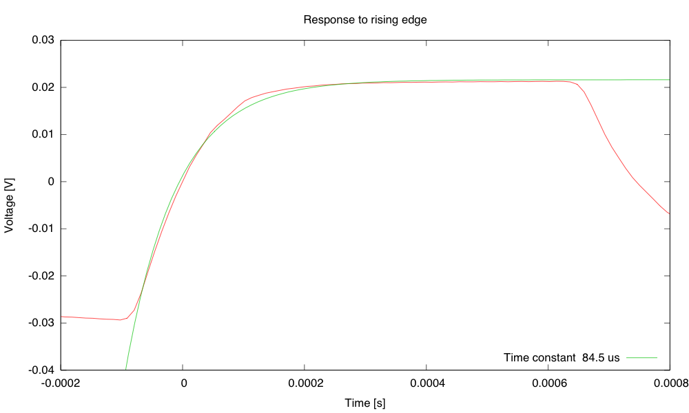
The circuit responds fairly quickly to a rising edge, roughly like having an RC time constant of 84.5µs.

The response to a falling edge is slower, roughly like an RC time constant of 207.8µs.
The response to rising and falling edges is quite different, because of the nonlinear nature of the diode. When we are charging the parasitic capacitance, we have a fairly large photocurrent to do it with, but when we are discharging, the current gets quite small as the voltage across the diode drops. With a linear system, response to a positive step and negative step would be identical, except for the sign.
Both response times are fast enough that the shape we were seeing for the pulse waveforms is due to changes in the opacity of the finger, not due to distortion or filtering in the amplifier. There is a sudden increase in opacity, followed by a gradual recovery as the blood flows through the capillaries and veins out of the thumb.
If I were to try the difference between LED-on and LED-off measurement, I’d want to have the LED on for at least 400µs, then off for at least 1ms. (I’d probably do on for 400µs, then off until the next 1/60s tick, making a 2.4% duty cycle for the LED.)
Note also that the 50mV swing here is much larger than the 3mV swing that I got from pulse measurements, so gain would have to be limited to avoid clipping.


")
 or hardback ($198)")

