Yesterday in 2-op-amp instrumentation amp, I worked through the analysis of the differential gain and common-mode gain for an instrumentation amp made from two op amps. There is a classic design of an instrumentation amp made from 3 op amps, and I was wondering how it compared in performance. Both instrumentation amp designs are available as fairly low cost integrated circuits, but the ones with better common-mode rejection seem to use the 3-op-amp design. Is there are reason for that?

3-op-amp instrumentation amp. Schematic drawn with SchemeIt (using PNG export rather than a screenshot, since I have no special characters).
The 3-op-amp instrumentation amplifier consists of two separately analyzable parts. The first stage consists of two op amps that provide high-impedance inputs and amplify the differential signal without changing the common-mode signal. The second stage is a differential amplifier that zeros out the common-mode signal and provides unity gain on the differential signal.
We can analyze the first stage by setting the currents through the resistors equal:

If we solve this for Va and Vb, we get

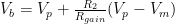
If we define 


The differential output of the first stage depends only on the differential input:

It may seem strange that I defined the common voltage so that I have an extra Vref floating around in the formula, but that simplifies out in the analysis of the second stage (which would not be the case if I had defined Vcomm as the just the average of Vp and Vm).
The differential amplifier that is the second stage can be described in terms of the two voltage dividers:
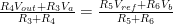
Solving this for Vout gives us

If we substitute in the values of Va and Vb (and use Maple plus some hand algebra), we can simplify to

At R3=R4 and R5=R6, we can simplify to

which is 
The worst-case common-mode gain with 1% errors in the resistors would be with R4 and R6 high, and R3 and R5 low, giving a gain of 0.02 (or vice versa, for a common-mode gain of –0.02). Comparing this to the 2-op-amp design’s common-mode gain of 0.04, we see that we gain a factor of 2 (6dB) in common-mode rejection by using an extra op amp.

")
 or hardback ($198)")


[…] wiring to the electrodes. With 130mV peak-to-peak common-mode voltage and a common-mode gain of 0.02 or 0.04, we’d have 2.6–5.2 mV of common-mode noise at the output of an instrumentation amp […]
Pingback by Common-mode noise in EKG | Gas station without pumps — 2013 July 8 @ 18:00 |
[…] resistors was unlikely to be reliable. I discovered (after doing calculations for 2-op-amp and 3-op-amp designs) that 1% tolerance on the resistors would produce poor common-mode rejection. In […]
Pingback by Some failed designs | Gas station without pumps — 2013 July 10 @ 12:23 |