Gas station without pumps

2015 May 15

Blood pressure lab part 2

Filed under: Circuits course — gasstationwithoutpumps @ 11:36
Tags: , ,

I spent long hours in the lab yesterday (10 a.m.–6:30 p.m.), because students were not as far along as I had thought by the end of Tuesday. I stay in the lab until all the students are finished, even if that is a couple of hours past when the lab should end. A lot of students were still debugging their breadboarded instrumentation-amp circuits 2 hours into the lab session, when I had thought that they would be soldering after at most an hour more breadboarding.

Debugging on both the breadboards and the soldered boards took a lot of time, but the problems were pretty much the standard ones:

  • power not connected
  • wire missing
  • wire to wrong location
  • power supply hooked up backwards to one of the chips
  • bent pin on chip not making contact with breadboard

A couple of groups asked me for debugging help but did not have a drawn schematic to work from.  As I had said earlier in the quarter, I would not help them debug unless they had a schematic to work from.  (I think in both cases the problem was that they had connected up one wire incorrectly, but without a correct schematic to work from, there was no way that they could detect the error.)  Some students have been a bit sloppy about trying to work out of their heads rather than putting things down on paper, and this sloppiness is beginning to be a problem for them.  It has mainly been the weaker students who have been being this sloppy, so perhaps it has been more the case that they have been trying to work out of other people’s heads—copying bits and pieces from other students rather than working things out themselves and then implementing it.

I won’t be helping students debug unless they have shown some effort at making their designs debuggable (like having a clean schematic before they wire things up).

I’m not 100% sure, but I think that all but one group got a soldered instrumentation amplifier working and a blood-pressure measurement run done with it.  The one group that didn’t get that far did have a breadboarded amplifier working.

There were some students missing due to illness, so I’ll probably have to arrange some time next week for make-up lab times.  I’m not sure when that can be.

2015 May 14

Blood pressure lab

Despite fairly poor prelab homework turned in, the first half of the blood pressure lab went well.  After seeing how poorly students were doing on breaking down the problem into pieces (perhaps the main transferable engineering skill I’m trying to get them to develop), I ended up giving them more explicit instructions on the board at the beginning of lab:

  1. calculate sensor voltage difference for 100mmHg with 3.3v power
  2. measure sensor voltage difference for 100mmHg with 3.3v power (also 0mmHg and -100mmHg)
  3. determine upper and lower inputs of voltage for instrumentation amp INA126P from the data sheet, using worst-case rather than typical specs (“worst-case” meaning the smallest remaining voltage range)
  4. use Vout-Vref = G(V+ – V) to determine maximum gain to avoid clipping if input swing is +-180mmHg (+-24kPa)
  5. compute needed gain resistor, wire it up (and virtual ground)
  6. measure voltage at output of instrumentation amp at 0, +100mmHg, -100mmHg
  7. compute gain needed in second stage to get maximum range (without clipping) at final output
  8. wire up op amp and measure final output voltage at 0, +100mmHg, -100mmHg
  9. What is Vout as function of pressure?
  10. record with the PteroDAQ a blood pressure measurement with pressure slowly decaying from 180mmHg down to 40mmHg (not too slowly, or your hand will get swollen).  Check for clipping at high end.  Check that you are using nearly the full range. Check that pulsations are visible when plotting the data.
  11. Use bandpass-filter.py to filter the first channel of the recording (later channels will be discarded)

I may have to put some version of these instructions in the book, though this sort of hand-holding is precisely what I’m trying to cut out in the “descaffolding”.  I’m afraid we’re training a generation of technicians rather than engineers—they’re good at following very explicit instructions, but not so good at breaking problems down into smaller problems.

With these explicit instructions, most of the students managed to get breadboard versions of the pressure sensor amplifiers working. I may have to help out bench 4, as it turned out that their pressure sensor seems to have a 0.7mV offset (which is pretty big—way out of spec).  They’ll have to decide whether to change benches to get a different sensor, compensate for the sensor offset electronically, or compensate for it in the post-processing of the data.  Any of these solutions would be acceptable, but they aren’t all equally easy.

The students needed less help than in previous years in the lab, so I think that having the students struggle with the prelabs, even if they don’t get the answers right, is helping make the lab time more efficient—they only have to get past a couple of misunderstandings, rather than trying to learn all the material for the first time in lab, as so many did the last couple of years.

In lecture on Wednesday, I went over blood pressure waveforms defining pulse rate, systolic pressure, and diastolic pressure, and talking about the frequency ranges of the pulse rate. I then explained to them how the filter program was run (many students still don’t know about the “<” and “>” conventions for standard in and standard out on command lines). I also showed the gnuplot trick that allows using standard out from a program in place of a file in a plot command:
plot '< python bandpass-filter.py < pressure.data' using 1:3 with lines

I did not explain how digital filters worked, but I did say why I chose Bessel filters (to preserve as much of the time-domain structure of the signal as possible).  In response to a question I also explained the effect that choosing 5th order filters had (the rolloff as f5 or f–5, rather than f1 or f–1 as with a first-order RC filter). I also explained that the computation required more and more precise numbers as the order got higher, and that 5th-order was a good tradeoff between needed precision and fast rolloff.

One thing that I didn’t get to was explaining that “filtfilt” does the filtering twice: once with time going forward and again with time running backwards. The time reversal cancels a lot of the distortion in the time domain (so the choice of Bessel filters is not crucial), but doing two passes also doubles the order of the filter, so that the rolloff is really f10 or f–10.

I did remember to tell students that they needed to have the scipy package installed in order to run the filter program, and that if their python was installed from python.org that they could probably just run “pip install scipy”. At least one student in the class is using the Anaconda installation of python, which already has scipy installed.

At the end of the lecture I had only 10 minutes left, so I did not get into the internals of instrumentation amplifiers (needed for the EKG lab at the end of the quarter) nor transimpedance amplifiers (needed for next week’s lab). Instead I covered the voltmeter impedance measurements I made last week, explaining how I did the measurements, how I did the fitting, and what the results were.  In particular, I mentioned that swapping the sets of leads changed the behavior, so the extra capacitance (beyond the 100pF of the meter itself) appears to be coming from the leads.  I sent the data files and gnuplot script to them via e-mail, after one student requested them.

2015 May 11

Lecture on pressure sensors

Today’s lecture was fairly straightforward:

  • Feedback on the audio-amplifier design report
  • Explanation of RMS vs. amplitude vs. peak-to-peak voltage measurements
  • How pressure sensor works
  • Wheatstone bridge, developed from voltage divider, with second fixed voltage divider to subtract off effect of supply voltage changes

I had wanted to get to the internals of how an instrumentation amplifier is built (the 3-op-amp and 2-op-amp designs), but that can wait until Wednesday.  I also wanted to do a demo of the pressure sensor with digital filtering, but that can wait until Wednesday also (and I forgot to bring in my KL25Z board today anyway).  Discussions of systolic and diastolic blood pressure will need to be done on Wednesday also—I’ll start with that, then move to the demo and show how to measure pulse rate and estimate the blood pressures from the recording.

The main feedback I gave on the design reports consisted of the following points:

  • A lot of students are still invoking V=IR without thinking about what the variables mean—they have to be talking about the voltage across and current through the same resistor, not some other random voltage in the system.  For the design they just did, it was impossible to know the voltage across the resistor until the power supply voltage was chosen, but the voltage across the resistor was not the power-supply voltage!
  • Many students did not justify their design choice for the power supply.  There were constraints on it (from the op-amp data sheet), and they should have chosen a voltage near the upper end, because they wanted as loud an output as possible, and the current limits increased with power-supply voltage.  One or two sentences that said those two things would have sufficed.
  • RC time constants have units (called “seconds”).  I showed the students that ΩF is seconds, by using the definition of Ω as V/A, A as C/s, and F as C/V.
  • Voltage gain, on the other hand, is unitless, being a ratio of two voltages.  I also explained the convention of showing what the ratios are of, express  gain in “units” of V/V.
  • The gain for their audio amplifiers needed to be designed (based on the current limits at the outputs and the loudspeaker impedance, divided by the calculated or measured input voltage to the amplifier).  Too many students got a hint from the group tutor for the class (that turned out to be wrong) and took it as a specification, rather than doing their own design.
  • Many students did not report their loudspeaker impedance, but it was essential for computing the voltage at which the amplifier would clip, and different students had different loudspeakers (some 6Ω and some 8Ω).
  • Paralleling op amps doesn’t increase the gain, merely the current limit for the amplifier.  So clipping happens at a higher voltage, but the gain for small signals remains unchanged.
  • Several students had misdrawn the gain control circuit, using the two ends of potentiometer symbol as if it were a variable resistor. I showed them both the standard symbol for a variable resistor and how to draw the potentiometer used as a variable resistor correctly.
  • Lots of students had very approximate gain measurements, because they had relied exclusively on the oscilloscope for measuring voltages.  I explained why the oscilloscope is inherently less accurate for measuring voltage than a voltmeter.
  • I explained that “surround sound” and “stereo” require different signals to the multiple loudspeakers—multiple speakers wired to the same signal don’t produce the aural position illusion that stereo and multi-channel sound does.
  • One of my pet writing peeves is the mixing up of prepositions in “substitute x for y” and “replace y with x”.  Note that what replaces what swaps positions in the two phrases.  When students mix and match to get “substitute x with y” or “replace y for x” I don’t know whether the verb or the preposition is dominating the meaning.  (In some dialects of English one or both of these phrases may be unambiguous, but they don’t seem to be consistently used in California, so I treat them as errors, rather than as dialect variations.)
  • Students are still starting numbers with periods.  I’ve told them repeatedly not to—numbers shouldn’t start with punctuation (other than a + or – sign), and there should always be a digit in front of any decimal point.
  • The triangle used as a ground symbol should always point down.

2015 May 8

First instrumentation-amp lecture

I started today’s lecture by returning a parts-and-tools kit to a student who had left it in lab yesterday—but admonished students not to tease him, since I had left my laptop in the classroom on Wednesday (a much more valuable item in a much less secure location).  That’s the second time in about a year that I’ve left my laptop in a classroom, which is something I never used to do.  (Of course, I’ve been using my laptop in classes a lot more than I used to, so it may not be that I’m getting old and forgetful, just that I have had more opportunities to leave it behind.)

I talked to the students about color-coding their wiring on their breadboards and on their prototyping boards.  The main lesson about color-coding was that black was reserved for ground, red for the positive power supply, and that I had four other colors available for them (blue, green, yellow, and white) in 22-gauge wire. They also have 24-gauge wire in the lab in white and orange, but I’m trying to discourage the use of 24-gauge wire, since it is not well held by the breadboards or KL25Z-board headers, and debugging the loose wires is a pain. I told them that I would not help them debug any boards that did not follow the red and black convention (red for all connections to the positive power supply and for nothing else, black for all the ground wires and nothing else). The other wires I suggested be color-coded on both the schematic and the board, based on the function. For example, all the virtual-ground wires might be white, all the input wires blue, all the wires after pre-amplification green, and so forth.  The exact color coding they use doesn’t matter, as long as they document it clearly and use it consistently.

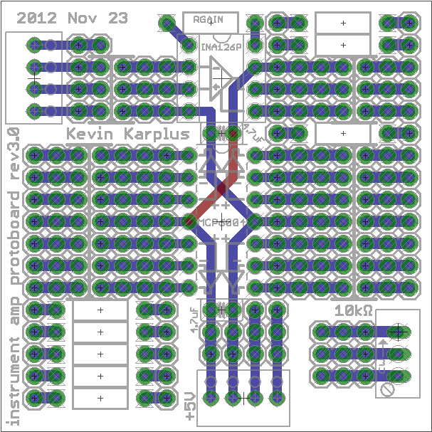
Hmm, it looks like I’ve never blogged about the newer version of the prototyping boards, so I should include a picture here. I did include a picture before in Twenty-first day of circuits class:

Instrumentation amplifier protoboard with circuit wired for the pressure sensor lab (top left connector to pressure sensor, bottom center connect or to Arduino)

Instrumentation amplifier protoboard with circuit wired for the pressure sensor lab (top left connector to pressure sensor, bottom center connect or to Arduino)

Here is a layout as represented in the Eagle program. Most of the PC board wiring is on the bottom layer, but the +5V power supply crosses over on the top layer (the red trace).  We’ll actually use the 3.3V supply on the KL25Z boards, not +5V power, but that is a minor detail.

This is a layout of the board as shown by Eagle.

This is a layout of the board as shown by Eagle.

The students are given a worksheet for them to plan their layouts on:

This layout worksheet is distributed to the class as a PDF file.  The students can either mark up the PDF with  PDF editing tools (which some students have done successfully in the past), or draw on it with pencils or colored pencils. Only the holes that wires can be placed in are shown—the holes intended for components are omitted from this worksheet.

This layout worksheet is distributed to the class as a PDF file. The students can either mark up the PDF with PDF editing tools (which some students have done successfully in the past), or draw on it with pencils or colored pencils.
Only the holes that wires can be placed in are shown—the holes intended for components are omitted from this worksheet.

I also talked about the importance of keeping wires short and close to the board, and of not routing wires over components.  I’m not expecting students to really internalize that message until they’ve had to debug an inaccessible chip in a nest of long wires, but I’ll put the message out there as often as I can.  I’ve already grumbled at several students in lab for having incomprehensible tangles of wires that were all one color, and I’ll continue to do so.

After the brief warm-up on wire colors, I talked about instrumentation amps as circuit blocks—how they differed from op amps, though both look like differential amplifiers. The key is that op amps have unspecified gain and offset, so need to be used in a negative feedback circuit, which turns them in to amplifiers for single-ended inputs, with inputs and outputs both referenced to a single Vref.  The instrumentation amp has a specified gain (usually controlled by a single external resistor) and a true differential input, with the output still referenced to an external Vref input.

I talked about the output voltage limits of the INA126PA chips they’ll be using, but I did not go to the data sheet to look up the limits, but made up some approximate ones.  I warned them that I was making up approximate ones and that they needed to look the real limits up on the data sheet, but I’m betting that over half the class won’t do that, preferring to believe numbers in their notes that they have been told are fake to looking up the real numbers.

I then had the students help me create a Vref source (a pair of resistors in a voltage divider, followed by a unity-gain buffer), so that we could take current from Vref without violating the voltage-divider constraint.

I showed the students the prototyping board worksheet and where all the components went, and explained how to use the worksheet to do layout before soldering.

I ran out of time, so on Monday, I’ll have to talk about the pressure sensors they’ll be using, and about what the inside of an instrumentation amp consists of (how to build one out of op amps).  I’ll want to do both the 3-op-amp design and the 2-op-amp design, because I’m going to have them build their EKGs in the last week using the 2-op-amp design.

2013 July 10

Some failed designs

For the past couple of days I’ve been exploring variations on the Blinky EKG project, looking at alternative approaches.

For example, I looked at the possibility of eliminating the most expensive part (the instrumentation amp), and decided that building my own instrumentation amp out of op amps and discrete resistors was unlikely to be reliable.  I discovered (after doing calculations for 2-op-amp and 3-op-amp designs) that 1% tolerance on the resistors would produce poor common-mode rejection. In Common-mode noise in EKG, I reported measurements of the common-mode noise with a fairly short twisted-pair connection to the EKG electrodes (close to a best-case scenario).  I concluded that the common-mode noise was way too large for using unmatched resistors to be a reasonable design, and using an integrated instrumentation amp is still a good choice.

Yesterday,  I tried turning the question around? Could I eliminate the op-amp chip?  Currently, I’m using the op amp for two things: to provide a unity-gain buffer to make the reference voltage source between the power rails, and to do second-stage amplification after a high-pass filter removes the DC offset. To eliminate the op-amp chip, I need to replace both these functions.

Replacing the unity-gain buffer seems fairly easy—I could use a low-drop-out linear regulator to generate the reference voltage instead of a voltage divider and unity-gain buffer, which would be somewhat smaller and cheaper (11¢ rather than 25¢ in 100s).  I didn’t have an LDO linear regulator at home, so I tried using a TL431ILP voltage reference instead.  Unfortunately, it provides very little current, and was unable to maintain the desired voltage when hooked up to the reference voltage input of the instrumentation amp.  I believe that a part like the LM317L would work fine, though, and I may want to test that at some point.

Removing the second-stage amplifier is more problematic.  I can set the gain of the instrumentation amp up to 2000 or 2500 easily, but any DC component in the input differential signal results in saturating the amplifier (with a 6v output range, and a 1mV AC signal, we’d need the DC bias to be less than 1mV also to avoid hitting the power rails).  I tried putting high-pass filters in front of the instrumentation amp, but with the long time constants needed to avoid filtering out the EKG signal, the filters never settled to within 1mV of each other, and the instrumentation amplifier always saturated.

So I need to keep the first-stage gain small enough to avoid saturation, which means I need a second-stage amplifier.  I could use a single op amp for the second stage and a low-drop-out regulator for the reference voltage, which would produce a cleaner output signal (since my voltage-divider-plus-unity-gain-buffer reference introduces noise from the power lines).  The MCP6001 single op amp is only 18¢ in 100s (rather than 25¢ for the MCP6002 dual op-amp), but the MCP6001 is only available as a surface-mount component, which I think is inappropriate for a first soldering project.  The MCP6001 + LM317L would cost about 4¢ more than the MCP6002.

I considered redesigning the Blinky EKG to use the LM317L voltage regulator and the MCP6002, even though half the MCP6002 would be unused, but the LM317L needs a 1.5mA load to maintain regulation, and that seems like a lot for a battery operated device—more than the op amp or the instrumentation amp use (though less than the LED when it is lit).  Even using a TL431ILPR voltage reference (10¢ in 100s) and the unity-gain buffer would only need 1mA, and would save one resistor.  There are lower-current voltage references, like the LM385, but they cost a lot more (42¢ in 100s).

The non-rechargeable CR2032 batteries I’ve been using for the Blinky EKG have about a 225 mAh capacity, and cost about 19¢ in 100s (but the design needs 2, so 39¢).  I could probably get about a 100-hour life with the present Blinky EKG design—I need to measure the current and the duty cycle of the LED to get a better estimate.

The Blinky EKG weighs about 20g (not counting the wires to the electrodes), which is a bit heavy for a pendant or brooch. Most of the weight is in the batteries, but a lighter battery would give up a lot of running time.   The smaller batteries also cost a lot more, probably because Digikey only buys them in quantities around 10,000 rather than in the millions. (From other suppliers CR2032 batteries cost about 60¢ in 100s, not under 20¢).

It has been good to fool around with the Blinky EKG design, as it has gotten me to think a bit about design issues other than the first can-I-get-it-to-work one.  I rarely get my students past that point in their thinking, and I’m not sure how I would do so, as there is always so much time pressure to cover new stuff, that they get very little time to tinker with designs.


Next Page »