The first Santa Cruz Mini Maker Faire seemed to go well. I did not get to see much of it, since I was busy at my booth most of the day, though I did get a break for lunch while my assistant Henry manned the booth, and I made a quick tour of the exhibits during that break, to see what was there, though with no time to chat with other exhibitors.
I understand that about 1800 people bought tickets to the Mini Maker Faire, which probably means there were over 2000 people on-site, including volunteers and makers. I hope the food vendors did OK—I ate at the Ate3One truck, since I never have before, but my opinion afterwards was that CruzNGourmet and Zameen have better food (both of those trucks are frequently on campus, and I’ve eat at each several times).
My day went pretty well, though I had one annoying problem, having to do with my pulse monitor display. When I set up the booth Friday evening, the pulse monitor was not working, and I thought that the phototransistor had somehow been broken in the rough ride in the bike trailer, so I brought the pulse monitor home, replaced the phototransistor and tested in thoroughly. Everything worked great, so I packed it more carefully for transport in the morning.
When I got everything set up Saturday morning, I found I had no electricity, though the electricity had worked fine the night before. After I finally tracked down a staff member with the authority to do anything about it, he suggested unplugging the other stuff plugged in and switching outlets. I turned out that the only problem was that the outlets were so old and worn out that they no longer gripped plugs properly—taping the extension cord to the outlet box so that the weight of the cord didn’t pull out the plug fixed the power problem.
Once I had power, I tested the pulse monitor, and it failed again! I used the oscilloscope to debug the problem, and found that the first stage transimpedance amplifier was saturating—there was too much light in the room, and even shading the pulse monitor didn’t help. By then, my assistant for the day (and my group tutor for the class on campus), Henry, had arrived and gotten the parking permit on his car, so I raced home on my bike to get resistors, capacitors, op amp chips, multimeters, hookup wire,and clip leads to try to rebuild the pulse monitor from scratch on the bread board.
When I got back to Gateway School, I tried a simple fix before rebuilding everything—I added a pair of clip leads to the board so that I could add a smaller resistor in parallel with the feedback resistor in the transimpedance amplifier, reducing the gain by a factor of about 30. This reduced gain kept the first stage from saturating, and the pulse monitor worked fine. Rather than rebuild the amplifier, I just left the pair of clip leads and the resistor in place all day—they caused no problem despite many people trying out the pulse monitor.
I think that I want to redesign the pulse monitor with a logarithmic first stage, so that it will be insensitive to ambient light over several decades of light. That should be an easy fix, but I’ll have to test it to make sure it works. I don’t think I’ll have time this weekend or next to do that, but I’ll add it to my to-do list.
I’ll need to think about whether to include having a logarithmic response in the textbook—that is certainly more advanced than what I currently include (just a transimpedance amplifier), which is already pushing students a bit. A transimpedance amplifier is a pretty common component in bioelectronics, so I really want to leave one in the course. I’m not sure a logarithmic amplifier is important enough or simple enough to include at this level (I don’t currently cover the non-linearity of diodes).

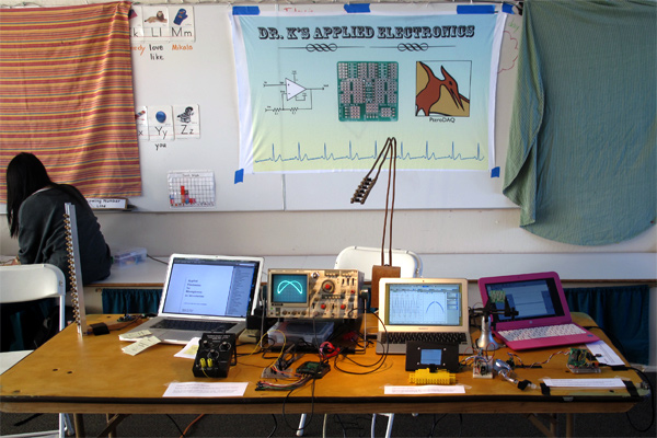
Here is the booth display with my assistant, Henry. I was permitted to use painter’s tape to attach the banner to the whiteboard.
The magenta laptop on right (which my family refers to as the “Barbie laptop”) was a used Windows laptop that I bought for testing out PteroDAQ installation on Windows. It was set up with PteroDAQ running all day, recording a voltage from a pressure sensor and a frequency from a hysteresis oscillator (as a capacitance touch center).
Just to the left of that was a fairly bright stroboscope, using 20 of my constant-current LED boards. To its left is my laptop, displaying the current draft of my book. Behind (and above) the laptop is my desk lamp, which uses the same electronic hardware as the stroboscope, though with only 6 LED boards, not 20.
In front of the laptop is the pulse monitor, which includes a TFT display in an improvised foamcore stand. I used just a half block for the pulse sensor, relying on ambient light (sunlight and the desk lamp) for illuminating the finger.
To the left of the pulse monitor was a stack of business cards for my book and sheets of paper with my email address and URLs for this blog and the book. I should have included the PteroDAQ URL as well, but I had forgotten to do so. I did tell a lot of people how to find PteroDAQ from the navigation bar of my blog, but putting it on the handout would have been better. Ah well, something to fix next year (if Gateway is crazy enough to do another Mini Maker Faire, which I hope they are).
I also had all my bare PC boards that I had designed and not populated, plus my two Hexmotor H-bridge boards, behind the business cards. One of the amplifier prototyping boards was displaying in the Panavise that I use for soldering.
On the far left of the table is my Kikusui oscilloscope and two function generators, set up to generate Lissajous figures. I let kids play with the frequencies of the function generators, take their pulse with the pulse monitor, and play with the pressure sensor and the capacitive touch sensor.
My booth was not the most popular of the Faire by any means (certainly the R2 Makers Club in the next booth was more popular), but I was kept busy all day and I talked with a lot of people who seemed genuinely interested in what I was doing, both with the UCSC course and as a hobbyist.


")
 or hardback ($198)")

