Today we continued looking at photodiodes, phototransistors, and LEDs, in the context of the colorimeter I had asked them to design. I think that next year I may go to the colorimeter first, and then to the more complex photospectrometer. Since the students weren’t familiar with spectrometry, starting with it was of no help, and all the other concepts (absorbance, irradiance, linearity of phototransistors, …) are more than enough to start with.
I started the class by collecting the work I had asked them to do on fleshing out the design of the colorimeter, which I have not read yet. I’ll have to grade their colorimeter designs before Wednesday, but I hope we can start learning some Arduino programming by then (probably just setup, loop, analogRead, Serial.print, and delay), rather than going over the homework.
After reading what they turned in for photospectrometer and photodiode assignment, I’m not setting my expectations very high for the colorimeters. I think (hope?) that the students are getting something out of the class, if not quite as quickly as I would like. I guess it takes some time for them to turn around habits of a lifetime and start generating new answers and new questions to answer, rather than just coughing back what the teacher said.
I wanted to get to Arduino programming today, but we didn’t get that far. I started with going over the homework, which was to find the resistor values for the following circuit:
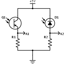
Simple circuits for measuring light with an Arduino. Update 2014 Feb 6: Q1 is intended to be an NPN phototransistor, not PNP as shown here!
- For Monday, 2014 Jan 27, as individuals (not groups), find a data sheet for the phototransistor WP3DP3BT. Also, select a cheap photodiode that is available in the same size and shape of package as the WP3DP3BT phototransistor and look up its data sheet.For the photodiode and the phototransistor, report the dark current, the voltage drop across the device (that would be collector-emitter saturation voltage for a phototransistor and the open-circuit voltage for a photodiode), and the sensitivity (current at 1mW/cm2 at λ=940nm, which is the wavelength where silicon photodiodes and phototransistors are most sensitive).Find a plot of the spectral sensitivity of a silicon photodiode or phototransistor (it need not be from the data sheets you found—all the silicon photodiodes and phototransistors have similar properties, unless the packaging they are in filters the light).
We want to make a circuit so that the full-scale (5v) reading on the Arduino corresponds to an irradiance of 204.8μW/cm2 at 940nm, so that each of the 1024 steps corresponds to an increment of 0.2μW/cm2. Remember that 1000μW=1mW. (We may not be able to use the full range, as the circuit should saturate at a somewhat lower value, depending on the saturation voltage or open-circuit voltage of the photodetector.)
For the circuits above, figure out what values of R1 and R2 to use to get the desired voltage range at A1 or A2. Look up what standard resistance values are available with 2% tolerance, and pick the nearest one. (Hint: Google is your friend for finding tables of information.)
In class on Monday, we’ll try building this circuit and seeing how it works with the Arduino Data Logger.
- By Wed 2014 Jan 29, redo the homework originally due on Monday, and turn it in on paper, typed, with the questions echoed and answered in full sentences. If you have any questions, discuss them on the class e-mail list. (I don’t want “I don’t know” to come up for the first time in class—you should have been asking for help over the weekend!)
The first thing I did in class was to go over that homework, giving them useful advice for adapting to college courses:
- No one computed R2 correctly. It didn’t bother me (much) that no one knew how to do it, but it did bother me that no one asked for help. I tried to impress on them that asking for explanation is not a sign of weakness, and that it should not be their goal to hide from view when they are confused about something. I don’t know whether this rant got through to them, but maybe if they hear it enough they’ll start asking questions in class or on the e-mail list.
- Only one person cited a source for the plot of spectral sensitivity for silicon photodiodes, and that more by accident than by design (the URL was printed by the browser). I explained the notion of plagiarism to them, how it was the most serious of academic sins, and how other engineering faculty (and me in other courses) might fail them for the course if they continued to claim other people’s work as their own (which is what an uncited figure is).
- I told them that they had to get very comfortable with the metric prefixes (only femto, pico, nano, micro, milli, kilo, mega, giga—they mostly won’t have much use for the smaller and larger ones) and their single-letter abbreviations. This is clearly something they need to work on, as one of the common problems in the homework was off-by-a-factor-of-1000 errors, as students changed µW to mW without scaling the numbers.
- I also impressed on them the importance of typing part numbers accurately—several had mistyped the part numbers for the photodiode they were specifying, and it took me a little detective work to figure out what they had really meant. Some had not provided part numbers at all, and I could not check whether their numbers were right (those students still got the computations wrong).
- Only three students found photodiodes that matched the specs: “a cheap photodiode that is available in the same size and shape of package as the WP3DP3BT phototransistor ” and that was sensitive to visible light. That meant finding a 3mm diameter, through-hole package.
- Several students found photodiodes in black packages that block visible light, which was not useful for this application. I explained why such parts exist (listening to IR emitters like in remote controls, without being swamped by ordinary light).
- Many students, having found photodiodes, could not accurately specify the sensitivity of the photodiode. Most just reported a current, without specifying the irradiance that caused that current. We went over the notion of linearity and that what we were interested in was the slope of the line, and that units were µA/(mW/cm^2). I mentioned that some spec sheets specified responsivity in A/W, but that had to be divided by the sensor area to get the more useful unit. I then had them compute the current at the specified maximum irradiance and the resistance that would be needed to get that current with 5v across the resistor. It took them a very long time (algebra skills are much lower than I would have expected for college freshmen—I have more sympathy now for the teachers of freshman physics), but they did eventually get the right answers for both the current and the resistance.
- I spent a fair amount of time letting students know that units were their friends, and that they should carry the units throughout the computation. I don’t know if the message got through, but I hope for their sakes that it will eventually.
Finally we could get to some new material. I asked them about monochromatic light sources for the colorimeter. Some thought of LEDs, but one student mentioned that he had seen incandescent bulbs as much cheaper than LEDs. It took me a second to figure out where this confusion came from—at the power levels used for room lighting, incandescents are indeed cheap and LEDs expensive. But we don’t need 5–20W of power—we’re not trying to cook what is in the cuvette. I pointed out that the maximum light level expected for the phototransistor was only 20mW/cm^2, so we needed only mW of power from the light, and at that light level, LEDs were much cheaper than incandescent bulbs.
I showed them the data sheet for a red LED, and explained some of the concepts. One concept was the difference between peak and dominant wavelength—the peak is where the light has the highest intensity, and the dominant is where it shifts to when multiplied by human visual sensitivity. I also explained what the “spectral line half bandwidth” was, though I did not go into the difference between half amplitude and half power—it was not important at the moment.
I then went over the symbol for a diode, how I remember that electrons move from the cathode to the anode (bring up vacuum tubes and cathode rays), and showing them a rough sketch of a diode current-vs-voltage curve. I showed them where various parameters were on the data sheet, though the particular LED data sheet I was using did not include the threshold voltage, just the forward voltage at high current.
The students brought up the notion of having multiple LEDs to get multiple colors, so I introduced them to RGB LEDs, showing both the common-anode and common-cathode circuits. They figured out, with a lot of prompting, which way round power had to be connected (the mnemonic device I used was that producing light required power, and power is voltage times current, so there had to be current flowing through the diode).
It doesn’t help that photodiodes are used backwards—the photodiode is reverse biased, and current flows only when light produces electron-hole pairs at the back-biased junction. I carefully did not talk about that while we were looking at the LEDs, as I’m sure it would have confused them.
By this point we were almost out of time, so I assigned a homework:
For Wed 2014 Feb 5, find a through-hole (not surface mount) RGB LED that is common-cathode, and design a circuit to power it from a +5V power supply. Make each color be as bright as possible without exceeding maximum current (you can leave a safety margin of up to 25%). Explain your design and how you sized the resistors for it.
I recommend using Digi-key’s search feature (looking for RGB LED) to see what parameters are usually most important to designers. I recommend using Digi-key’s free web tool SchemeIt for drawing a circuit diagram. They don’t have an RGB LED symbol, but you can make one out of 3 LED symbols (I’d use variant 1 for that).
Bonus: find an RGB LED that is common-anode, and do the same design exercise with it. (If Digi-Key’s search doesn’t turn up a part, try using Google.)
I did show them the prototype colorimeter I made over the weekend out of black foamcore, but did not have time to demo it. I was also going to demonstrate the use of vernier calipers to measure the cuvettes, but again ran out of time. I’ll probably do a blog post about my first colorimeter prototype later this week, but I’ll need to get to bed early tonight, as I’m grading an elementary school science fair early tomorrow, and I’ve got a bad cold that is leaving me exhausted. (I’ll have another science fair to judge Thursday morning, so this is not a good week for me to have a cold.)

")
 or hardback ($198)")


[…] Seventh day of freshman design seminar […]
Pingback by Twelfth day of freshman design seminar | Gas station without pumps — 2014 February 19 @ 23:12 |
[…] had made a prototype colorimeter out of black foamcore,which I mentioned in Seventh day of freshman design seminar. I’d meant to blog about it earlier, but I got a bad virus infection of some sort and was out […]
Pingback by Colorimeter design—almost working | Gas station without pumps — 2014 February 26 @ 00:34 |