I decided to look a little more at automatic measurement of conductivity of a saline solution again, continuing the ideas in Towards automatic measurement of conductivity of a saline solution.
The idea is a simple one: make a voltage divider consisting of the pair of electrodes on one leg and a known resistor on the other, put a square wave in, and measure the output voltage. By making the measurements synchronous with the square wave, we should be able to eliminate the DC component and look just at the high-frequency response. The output should be proportional to 
See Better measurement of conductivity of saline solution for the variation in the magnitude of impedance with frequency for polarizable stainless steel electrodes and Making Ag/AgCl electrodes for non-polarizable silver/silver-chloride electrodes. For polarizable electrodes, we probably want to stay over 10kHz, which shouldn’t be a problem with the Freedom KL25Z board, but could be pushing the Arduino A/D converter. I think that the Arduino scales down the 16MHz clock to 125kHz for the A/D conversion (it needs to be ≤200kHz), and at the auto-triggered rate of 13.5 clock cycles per sample, that is only 9,259Hz sampling rate. With single samples, at 25 clocks per sample, we’re down to 5kHz sampling. (The Freedom KL25Z board looks like it could do over 300kHz at 16 bits.)
I suspect that the thickness of the oxide coating on 316L stainless steel varies a lot with conditions (thicker in oxidizing conditions, thinner in reducing conditions), so stainless steel may not be the best choice of material for a conductivity probe, even though it will contaminate solutions less than many other probe materials. One commercial sensor (Omega CDE-45P) uses titanium for its electrodes “for greater chemical resistance.”
The commercial sensor uses a 4-electrode design, with two sense electrodes close to, but not touching, the drive electrodes. They claim that this allows maintaining a constant drive level despite fouling of the electrodes. I can see how that would be useful in a continuous monitoring application, where the characteristics of the electrodes would change over time. I’m curious how well it works—something else for me to play with.
To avoid electrolysis at the electrodes, we want there to be no DC component to the drive signal, so the sense electrode should be biased to half way between the extremes of the square wave. The crudest way to do this would be just to put a voltage divider between the power rails, and use the Thévenin equivalent resistance as R. A much fancier way would be do a low-pass filter of the drive signal and use that to bias a patch-clamp amplifier—something like this:

Possible circuit for the front end of a 2-electrode conductivity tester. U2 is a unity gain amplifier that monitors the drive electrode and feeds the RC low-pass filter, which sets the DC bias voltage for the sense electrode through the current-to-voltage amplifier made with U1.
A design like this should work so long as the drive signal remains between the rails of the op amp power supply. The output is proportional to the current through the electrodes, which is 

The resistor R3 keeps the current small enough that the output of the of the current-to-voltage converter stays between the rails. Both R2 and R3 could be increased to reduce the current, as long as R3 ≥ R2. If R2 is set too low, then the signal for low-conductivity solutions will be too small to measure reliably, while if R2 and R3 are set too high, then high-conductivity solutions will be difficult to measure, being too close to the full-scale range of the analog-to-digital converter.
Of course, if we know the high and low voltages of the input signal, we can get rid of the low-pass filter and amplifiers:
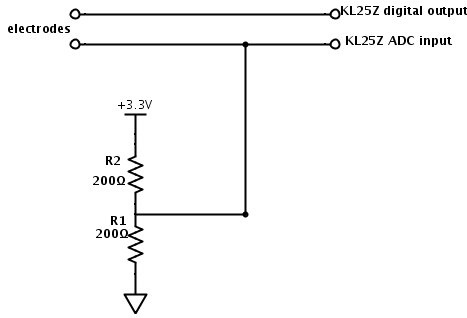
Simplified circuit for conductivity tester.
With the simplified circuit, the two resistors form a voltage divider, so that we have a Thévenin equivalent that is half the resistance to the voltage midway between the high and low voltage. This makes the output $V_{out} = \pm \frac{V_{hi}-V_{lo}}{2}\frac{R/2}{Z+R/2}+ \frac{V_{hi}+V_{lo}}{2}$. This circuit is simple enough for the freshman design seminar, so I should check out how well it works.
The KL25 chip has regular-drive and high-drive digital outputs, rated for 5mA and 18mA respectively (with a 3.3v power supply). PTB0, PTB1, PTD6, and PTD7 I/O have both high drive and normal drive capability selected by the associated PTx_PCRn[DSE] control bit. All other GPIOs are normal drive only.
I started out playing with the PWM outputs on the KL25Z board, because the interface for making nice square waves is so simple. I found that the MBED pwmout_api.c file has some serious errors in it: the periods are off by 1 count and the default prescaling they chose does not allow integer numbers of µsec. I fixed the off-by-one errors on period and changed the prescaling to be 48MHz/16=3MHz for the timer. This allows integer arithmetic for setting in µsec and msec, but limits the period to 216/3 µsec = 21845µsec (instead of ~87.381 msec).
I have not yet figured out a good way to do analog-to-digital sampling triggered by both edges of the PWM output. I may end up using interrupts on the rising edge (timer interrupt, setting TOIE=1) and on the falling edge (channel interrupt, setting CHnIE=1).
Before that, I should probably make up some salt solutions and check that the waveforms look ok with the electrodes. Let’s see—1M NaCl would be 58.44 g/l, or 29.22 g for 500ml, and 0.1M would be 2.922 g for 500ml. I made some 1M NaCl (probably a little lower concentration, since I used commercial table salt, which generally has a few other thing mixed in with the NaCl).
I set up the simpler 2-resistor circuit, and wrote a little program for the Freedom KL25Z board that produced square waves, using the touch sensor to get 2 virtual buttons to increase or decrease the frequency. I examined the waveforms with the Bitscope USB oscilloscope (using the differential probe, though that wasn’t really necessary here).

At 1kHz (1000µs period), the input square wave (yellow) shows a little rounding and the output across the resistor (green) shows a bit of sharpening, both due to the capacitance of the polarizable electrodes. (click to embiggen)
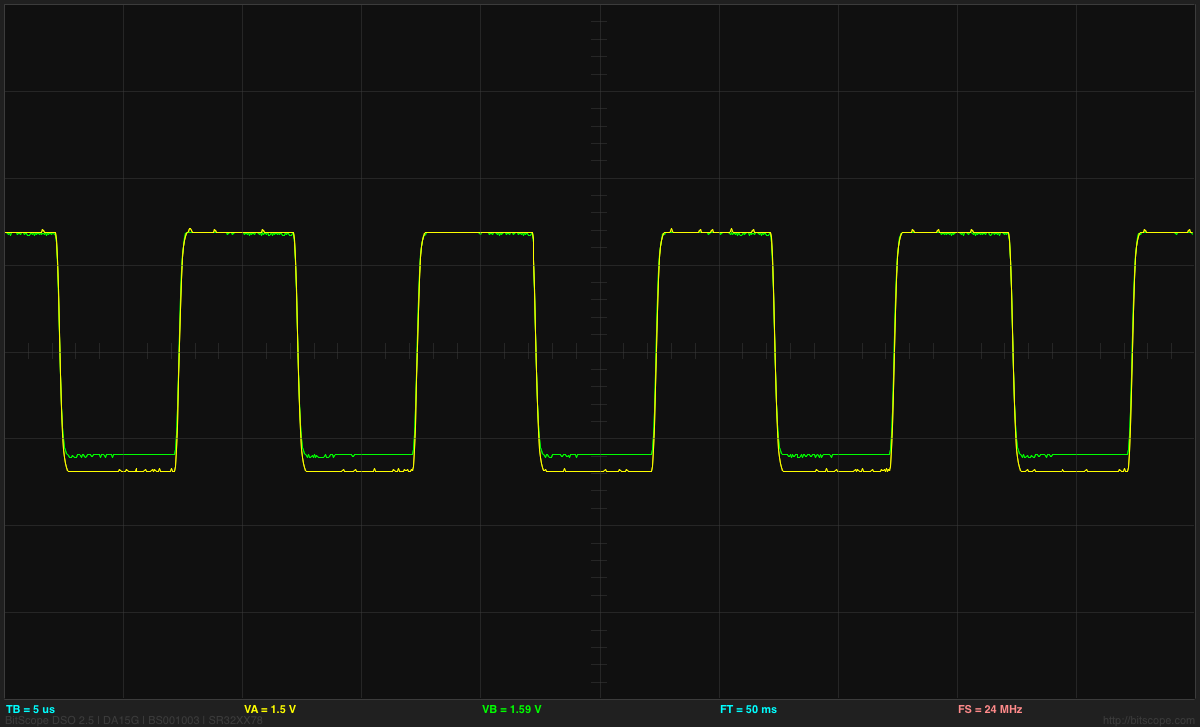
At 100kHz, both the voltage and current waveforms look like pretty good square waves.
I made a table of measurements using the Bitscope cursors (a rather tedious method, but my son hasn’t made the Data Logger code for the Freedom KL25Z yet, and I’m too lazy to do it myself). The Bitscope showed considerable distortion of the 500kHz signal (not evident on a higher-bandwidth scope, so probabably due to the limitations of the BitScope amplifier—see my post on the Bitscope differential probe).
| period µs | freq kHz | Vin |
Vout |
|---|---|---|---|
| 2 | 500 | 2.74–2.948 | 2.52–2.633 |
| 5 | 200 | 2.812 | 2.56–2.605 |
| 10 | 100 | 2.763 | 2.54–2.60 |
| 20 | 50 | 2.763 | 2.50–2.60 |
| 50 | 20 | 2.773 | 2.48–2.624 |
| 100 | 10 | 2.763 | 2.42–2.674 |
| 200 | 5 | 2.77 | 2.36–2.732 |
| 500 | 2 | 2.72–2.763 | 2.24–2.849 |
| 1000 | 1 | 2.70–2.782 | 2.02–3.00 |
| 2000 | 0.500 | 2.62–2.854 | 1.78–3.211 |
| 5000 | 0.200 | 2.56–2.941 | 1.34–3.642 |
| 10000 | 0.100 | 2.48–3.006 | 1.06–3.793 |
| 20000 | 0.050 | 2.40–3.072 | 0.74–4.069 |
Once the period gets longer than about 200µs, exactly when you look at the signals begins to really matter, as the voltage and current waveforms deviate more from a square wave. Below are the waveforms at 50Hz, which is as slow as I measured:

50Hz square wave input (yellow) does not look very square on the oscilloscope. The green output waveform (which is the current through the electrodes) shows the effect of the capacitance of the polarizable electrodes. (click to embiggen)
Using the results for the 100kHz square wave, I get that the resistance of the 1M NaCL solution with the 316L stainless steel electrodes is about 4.69Ω, similar to the 5.5Ω I estimated from sine-wave measurements last August (with a different 1M stock solution, not as carefully made). I can’t get this into any sort of standard unit, except by calibration with known reference solutions, since the value measured depends on the geometry of hte electrodes. The same is true of commercial conductivity testers also.

")
 or hardback ($198)")


[…] More on automatic measurement of conductivity of saline solution, I suggested using a simple voltage divider and a microcontroller to make conductivity measurements […]
Pingback by Still more on automatic measurement of conductivity of saline solution | Gas station without pumps — 2013 December 25 @ 01:37 |
[…] More on automatic measurement of conductivity of saline solution looks at waveforms for square waves generated using PWM on the KL25Z board. In this post I found that 100kHz square waves would work well. […]
Pingback by Using KL25Z for measuring salinity | Gas station without pumps — 2013 December 25 @ 20:09 |
[…] More on automatic measurement of conductivity of saline solution […]
Pingback by Blog stats for 2017 | Gas station without pumps — 2018 January 1 @ 11:47 |