Gas station without pumps

2015 October 6

Crawlspace ventilation—better low-voltage handling

Filed under: Uncategorized — gasstationwithoutpumps @ 10:10
Tags: , , ,

In Crawlspace ventilation again, I mentioned the problem that I was having with the fans whining if the power supply could not provide enough power:

With the 8Ω series resistance, the 4-fan load had a hard time getting started, and whined a bit before starting. Once one of the fans got up to speed and reduced its current draw, the others quickly came up to speed also. The regulated voltage was only 4.9V, and fluctuated a bit, rather than the constant 5.02V with smaller loads or less series resistance between the 9V power supply and the regulator.

With the 10Ω series resistance, the 4-fan load could not start at all, but just whined. The output of the regulator was only 2.2V while the fans were stalled. If a 4th fan was added while 3 fans were already running, the fans ran, but with a 4.11V regulator output. (The three fans had already reduced the regulator voltage to 4.99V).

I may have a little trouble with the fans each morning as the power comes up gradually—they may have trouble starting if the panel is not yet putting out enough power. If that turns out to be a problem, I may need to add some circuitry to detect low voltage on the regulator and turn off one or more fans.

The fans I’m using have brushless motors, which means that they include electronics to set the speed of the fan.  Based on the electrical noise I see on the power line, they appear to have a constant frequency independent of whether the fan is spinning or not. This simple design for the electronics is cheap, but not as good as a design that detects the speed of the motor and optimizes the phase and frequency of the rotating magnetic field to maximize torque or efficiency. The whining at low power when the fan is not turning seems to be at the frequency at which the fan is expected to spin with a 5V supply, but I’ve not used a microphone to check.

I tried two different approaches to handling the low-voltage problem:a power-on-reset chip and a simpler FET circuit of my own design.

The first design was to use a power-on-reset chip and an nFET to turn off the motors when the voltage was too low.  This was inspired by the standard Miller engine used in solar motor toys to harvest energy from low-current solar cells, store it in a capacitor, and discharge the capacitor through the motor when there was enough charge. This did not work well, as the voltage from the regulator quickly got up to 5V when there was no load, but dropped almost immediately when the fan was turned on, causing the reset chip to turn the fan off again. The chip I was using, MCP100-450DI/TO has only 50mV of hysteresis, so it would turn off again almost as soon as it turned on, and then wait for 0.3 s before turning on again.  The 50mV hysteresis meant that I’d need a large storage capacitor to get the fans past their initial high-current startup—I estimated around 15F, which would be an expensive supercapacitor.  Without a huge capacitor,  this circuit resulted in pulsed whining when the power supply was not capable of delivering the full 5V, which was even more annoying than the steady whine.

The second design I tried was just using the exponential turn-on of an nFET to provide full current when the voltage was high enough, but limit the current to very low levels when the voltage was insufficient:

The large capacitor on the gate keeps the transistor on for a while even after the voltage starts dropping.

The large capacitor on the gate keeps the transistor on for a while even after the voltage starts dropping.

One essential part of the circuit was the large electrolytic capacitor on the gate voltage.  Without it, the voltage on the gate would rise to a point where the motors were struggling to start and stay there (when the power supply was provided with too low an input voltage). With the capacitor in place, the fans would continue to get current even as the voltage dropped a bit, giving them enough time to spin up and reduce their current load.  Eventually the gate voltage would drop enough to start pinching off the current and the fans would hesitate and need to be spun up again. The result was that the fans would start even with a large series resistance between the 9.26V power supply and the input to the regulator (16Ω and sometimes even 32Ω), but not run smoothly unless there was enough power being delivered to the power supply for their continued running.

A smaller capacitor (220µF) worked also, but the fluctuation in speed happened more rapidly.  Much smaller (33µF) did not filter the power-supply fluctuation enough to hold the fans on long enough to start up cleanly.

Adding capacitance across the 5V terminals decreased the electrical noise, but did not seem to change the behavior of the circuit.

The flyback diode (the BAW62) is probably not necessary with these fans, since the brushless-motor controller built into the fans undoubtedly has its own flyback diodes.  I saw no evidence of inductive spikes when turning off the nFET.

So far I’ve only breadboarded the nFET control circuit, but I’ll probably solder it up later this week, when I get some time.
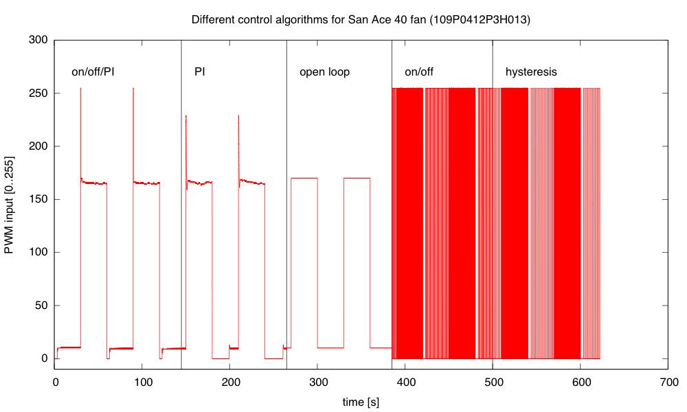
2015 September 27

Crawlspace ventilation again

Filed under: Uncategorized — gasstationwithoutpumps @ 22:53
Tags: , , ,

In Crawlspace ventilation, I talked about wiring up some little 5V fans, a voltage regulator, and a solar panel to ventilate the crawl space under my house. Today I wired up another regulator board (with a green LED this time).  The wiring is a bit neater this time (practice helps!):

I soldered the components to the prototype board first this time, then added the wires, rather than trying to do both at once. As before, the end with a one screw connector is the 12V input, and the other end has a pair of GND connections and a pair of 5V connections.

I soldered the components to the prototype board first this time, then added the wires, rather than trying to do both at once. As before, the end with a one screw connector is the 12V input, and the other end has a pair of GND connections and a pair of 5V connections.

The circuit is the same as before, with the addition of a green LED to light up when there is power.

The circuit is the same as before, with the addition of a green LED to light up when there is power.

I tested the regulator with 1, 2, 3, and 4 of the fans: http://www.digikey.com/product-detail/en/FAD1-06025BBLW12/Q620-ND/2600074  I got a constant 5.02V output independent of the load when powering the regulator from a 9.25V power supply (nominally 9V).  The 9V supply is pretty beefy (6A capability), so the tiny loads of the fans did not cause much change in the voltage at the input to the regulator (maybe 0.02v IR drop).

I was curious what a larger IR drop in the wiring to the regulator would do, so I tried putting a resistor between the 9.25V supply and the regulator:

resistance # fans V_in I_in
1 9.14V 60mA
2 9.02V 120mA
3 8.88V 190mA
4 8.76V 250mA
1 9.01V 60mA
2 8.76V 125mA
3 8.48V 195mA
4 8.19V 270mA
1 8.75V 63mA
2 8.22V 130mA
3 7.5V 220mA
4 6.7V 320mA
10Ω 1 8.61V 65mA
10Ω 2 7.85V 140mA
10Ω 3 6.94V 230mA
10Ω 4 6.4V 290mA

With the 8Ω series resistance, the 4-fan load had a hard time getting started, and whined a bit before starting. Once one of the fans got up to speed and reduced its current draw, the others quickly came up to speed also. The regulated voltage was only 4.9V, and fluctuated a bit, rather than the constant 5.02V with smaller loads or less series resistance between the 9V power supply and the regulator.

With the 10Ω series resistance, the 4-fan load could not start at all, but just whined. The output of the regulator was only 2.2V while the fans were stalled. If a 4th fan was added while 3 fans were already running, the fans ran, but with a 4.11V regulator output. (The three fans had already reduced the regulator voltage to 4.99V).

It seems like the voltage regulator works fine as long as the input voltage is at least 7V (as claimed in the specs), but if the IR drop in the wiring to regulator is enough to drop the voltage below 6.8V, the regulator may not be able to supply enough current to start the fan motors. Each fan takes about 80mA@5V (400mW) once up to speed, so the regulator seems to have an efficiency around 74%—considerably less than what I expected from the spec sheet.  I’ll have to investigate that more closely.

I may have a little trouble with the fans each morning as the power comes up gradually—they may have trouble starting if the panel is not yet putting out enough power. If that turns out to be a problem, I may need to add some circuitry to detect low voltage on the regulator and turn off one or more fans.

2015 September 26

Crawlspace ventilation

Filed under: Uncategorized — gasstationwithoutpumps @ 23:03
Tags: , , ,

I have a crawl space under my house that gets rather damp—my house is built where an aquifer comes to the surface, and in most years the water table is only a few centimeters below the surface.  (Because of the 4-year drought, the water table is currently about a 30cm below the surface.)  A few years back I had a solar panel put on one side of the house, connected to 12V fans in the crawl space to exhaust air from the wettest part of the space, but the fans stopped working shortly after the installation.

I have two conjectures about why the fans failed:

  • The 12V DC wires from the solar panel to the fans were broken somewhere, and so there is no voltage at the fans.
  • The voltage from the solar panel exceeded the voltage rating of the fans enough to burn out the fans.

I’m claustrophobic enough that I’ve never wanted to crawl around down there to try to debug the problem or replace the fans, so the installation has been non-functional for a few years.

So next week I’m having my general contractor/carpenter redo the fans so that they will be more maintainable.  The main thing is to make hinged “doors” for the vents, so that the fans can be accessed from outside the house, without having to crawl the width of the house under a very low ceiling.  Having access to both ends of the cables also makes checking them for continuity easier, and makes it possible to pull new cables if needed without crawling under the house.


I’m also going to change how the fans are hooked up.  Instead of using 12V fans, I got a number of little 5V fans that are very quiet (18.1 dB) but have reasonable airflow (13.1 CFM): http://www.digikey.com/product-detail/en/FAD1-06025BBLW12/Q620-ND/2600074 They are rated for 70,000 hours, but are only rated down to –10°C (good enough for Santa Cruz).

Putting 4 of the little fans blowing air through holes in the “door” should provide me with about 50 CFM (cubic feet per minute) at about 24dB.  With two such doors (8 fans) I should get 100CFM at about 27dB.  That is more air flow for the noise level than any single-fan solution that I found.

I’m going to put a 5V switching regulator on each door, so that the voltage from the solar panel can fluctuate wildly and the fans can still run at a constant voltage. The OKI-78SR regulators can accept anything from 7V to 36V and produce 5V output with about 90% efficiency. They only handle 1.5A, but 4 of the fans is only 0.6A, well below the rating. Each regulator will be delivering about 3W to the fans, so the power needed from the panel is only about 7W.  I believe that the panel was a 50W panel, so the fans should run even when the sky is overcast, though not at night, unless I add a rechargeable battery to the system.   (There was originally a lithium iron phosphate battery in the system, with a charge controller, but I repurposed it for other projects and it has since failed.)

I also don’t have to worry about the IR drop in the cabling to the vent fans, as it will not be anywhere near enough to drop the voltage below 7V when the solar panel is producing power.

Here is the circuit:

The Schottky diode is there to prevent damage from accidentally wiring the power backwards—I happened to have a couple on hand.

The Schottky diode is there to prevent damage from accidentally wiring the power backwards—I happened to have a couple on hand.

I wired up one of the regulators on a prototype board:

My soldering is pretty sloppy on the prototyping board—I've gotten so used to doing custom PC boards for everything that running wires and joining them to components seems a bit strange. There's not much point to a custom board for only 2 instances, though, especially with such a simple circuit.

My soldering is pretty sloppy on the prototyping board—I’ve gotten so used to doing custom PC boards for everything that running wires and joining them to components seems a bit strange. There’s not much point to a custom board for only 2 instances, though, especially with such a simple circuit.

In this rather low-quality photo, the 12V input (7V–36V) comes in through the two screw terminal on the right, and the 5V output is on the the two front screw terminals on the left, with ground on the two back screw terminals on the left.  I added male headers for +5V, Gnd, Vin, so that I could later add monitoring circuitry for remote monitoring or logging the voltages, if I felt like adding that.  It might be interesting to log the voltages for a year.

I’m considering adding a resistor and an LED to the 5V output, so that there will be a visible indicator of power, but I’m not sure it will be worth the effort, since the board will usually not be visible and if I open the panel for debugging, I can use a voltmeter easily enough.

2015 January 4

Thermal control loop working (sort of)

Classes start tomorrow, so I spent yesterday making sure that the incubator control project was feasible. I had gotten the fan feedback control working well back in September, but I’d put the project aside for Fall quarter and only got back to it this week.  As a reminder, here are the previous posts on the project:

Here is the interior of the styrofoam box, with the lid open.  The 6"×12" aluminum plate covers the bottom.  The thermistor is on the left, propped up by a rubber foot, the resistor in is the center, and the fan is sitting on a foam pad on the right. (The foam is to reduce noise until I can get the fan proper mounted in a baffle.)

Here is the interior of the styrofoam box, with the lid open. The 6″×12″ aluminum plate covers the bottom. The thermistor is on the left, propped up by a rubber foot, the resistor in is the center, and the fan is sitting on a foam pad on the right. (The foam is to reduce noise until I can get the fan proper mounted in a baffle.)

I left the foam out this time, which made for a somewhat noisy fan, and I still haven’t built a baffle—I’m still using the bent-wire-and-paper deflector shown in the photo. What I worked on yesterday was the software—since the temperature changes are fairly slow, it takes a long time to tune the control loops.

One thing I did was to try to reduce measurement noise further on the thermistor measurements. I now add 60  analog-to-digital readings. They’re 10 bits on the Arduino-compatible board (a Sparkfun redboard), so adding 60 still fits in an unsigned 16-bit word. I now get noise of about ±0.05°C, which is half the least-significant-bit of the converter.  I doubt that I can do better in precision without switching to a processor with a better analog-to-digital converter, though I could do digital filtering with a 1Hz low-pass filter to smooth out the remaining noise.

I copied the fan feedback control loop (with the anti-windup provisions) described in Improving feedback for fan for temperature control, but made two changes:

  • I changed the integration time and K_p for the thermal control loop, since the temperature response is much slower than the fan response.
  • Because of the huge asymmetry in the temperature response (the resistor and metal plate can heat up much more quickly than they cool down), I turn off the heater the moment it gets over temperature, no matter with the PI loop suggests, but I only switch to full-on when the air temperature is 3°C too cold. For the fan, I used a symmetric window around the set point for using the PI loop rather than full-on/full-off.

Here are some results from tuning experiments:

The blue curve switched to PI control at 23.5°C, the other two at 22°C. The green curve has pretty tight control over the temperature, but does overshoot a bit.

The initial temperatures were not all identical, because I wasn’t always willing to let everything cool down all the way to room temperature after each tuning run. I could only do about 1 tuning run an hour, which could pose problems for the freshman design seminar, as we don’t have long lab times—only the 70-minute lecture-schedule meeting times.

I continued the best of those runs with another step, up to 35°C, then let it cool down.

The step to 35°C has more ringing than the step to 25°C. I terminated the run before it had finished cooling, because the 32-bit µs timer wrapped around.

The cool-down at the end fits a 0.0069 °C/s line better than it fits an exponential decay to the ambient temperature.  If I do fit an exponential decay curve, I get a time constant of around 1975 seconds.

A simple thermal-resistance, thermal-capacity model is not a very good one for predicting how the system will behave, particularly since we’re not measuring the temperature of the large thermal mass (the aluminum plate and power resistor), but of the air, which has a large thermal resistance from the plate.  The time constant for the aluminum-air transfer is larger than the time constant for the electricity-aluminum transfer, which is why we get so much overshoot when we turn off the power to the resistor—the aluminum plate has gotten much hotter than the air, and continues to transfer heat to it, even though no more heat is being added to the aluminum.

Still, it is worth seeing what we get if we model the box a simple thermal mass and thermal resistor. The steady-state 35°C seems to need about 9W (PWM of 51/256) and the 25°C 3W (PWM of 17/256) with an ambient temperature of about 19°C, implying that the styrofoam box has a thermal resistance of about 1.9°C/W.

To see what is really going on, I’ll have to heat the box to 35°C, then start the cool down with a reset 32-bit timer.

Single-step warming from 16.9°C to 35°C. The steady state at 35°C is about 9.32W, for a thermal resistance of 1.8°C/W. The rise of 0.0451°C/s at 45W implies a thermal capacity of 998 J/°C.

Heating at 45W (9V, 1.8Ω) results in a temperature rise of about 0.0451 °C/s. This warm-up rate at 45W implies a thermal capacity of about 998 J/°C. We may want to adjust our thermal capacity estimate, since some of the 45W put in escapes through the box—maybe about 3–4W at the temperatures where the rise was measured. This reduces the thermal capacity estimate to about 910 J/°C.

The cool down from 35°C starts out as a straight line (about -0.0074°C/s or -26.5°C/hour), but gradually starts behaving more like the exponential we would expect from a thermal-resistance and thermal-capacity model.

The time constant for the cooling is about 1380s, but the initial cooling is too slow for a simple exponential.

The time constant for the cooling is about 1380s, but the initial cooling is too slow for a simple exponential.

The time constant of 1380 s, combined with a thermal capacity of 910 J/°C gives a thermal resistance of 1.5 °C/W, a bit lower than the 1.8°C/W I estimated from the steady-state power.

I continued the cooling (with the timer wrapped around) to see if I got a clean exponential at low temperature differences:

The exponential seems to fit well here, with a time constant of 2300s.  Combined with the 910 J/°C, this gives a thermal resistance of 2.5°C/W, which seems a little high compared to the other estimates.

The exponential seems to fit well here, with a time constant of 2300s. Combined with the 910 J/°C, this gives a thermal resistance of 2.5°C/W, which seems a little high compared to the other estimates.

So I’ve made some progress on the thermal control loop (though I’d like to reduce the overshoot and ringing) and I have a crude model for the box: a thermal mass with capacity about 910 J/°C and thermal resistance 2±0.5 °C/W.

Still on my to-do list for this project:

  • Consider using a PID controller for the temperature to get faster response without overshoot.  (If I can reduce the noise problem.) I should be able to reduce the noise with a digital filter, but I’m already pushing well beyond what I’m comfortable covering in a freshman class. Tuning a PID controller is even trickier than tuning a PI controller, which is already going to take most of the quarter to teach.
  • Design and build baffling for the fan to get better airflow in the box. This might be a good thing to get students to do, particularly if we can get them to learn how to use the laser cutter. But even handsaws would suffice, given some thin plywood or masonite, some angle irons, and nuts and screws.
  • Figure out how to get students to come up with workable designs, when they are starting from knowing nothing. I don’t want to give them my designs, but I want to help them find doable subproblems. Some of the subproblems they come up with may be well beyond the skills that they can pick up in the time frame of the course. The more I work on this project, the more I realize that I and the students will have to be happy with them having explored the options, without getting all the problems solved.
  • Add changes to the cumulative error term whenever KP or TI are changed, to keep the PWM output the same after the changes—currently changing any of the control loop parameters adds a huge disturbance to the system. I don’t know how important this is—I’ve been doing my tuning of the thermal loop by recompiling, rather than by changing parameters on the fly. The quick changes were handy for the fan loop, where I could see things happening quickly, but for the thermal loop each experiment took about an hour, so there was no need for a fast parameter change.
  • Research control algorithms other than PI and PID, particularly for asymmetric systems like the temperature control, where I can get fairly quick response to the inputs when heating, but very slow response when cooling. The asymmetric window for switching between on/off and PI control seems to have helped here, but there is probably a more principled way to handle asymmetric control inputs. Maybe I should ask some of the control-theory faculty for some pointers.
  • Develop a more detailed thermal model with separate components for the aluminum plate and the air in the box. It may be worth adding another thermistor, taped to the aluminum plate, to monitor that temperature. The extra thermistor would also allow much tighter temperature control, avoiding overshoot on air temperature.


2014 September 20

Improving feedback for fan

Filed under: freshman design seminar — gasstationwithoutpumps @ 12:22
Tags: , , , , , ,

I wanted to look at the step response of the fan and of the heater, so that I could see if I could derive somewhat reasonable control parameters by theory, rather than by cut-and-try parameter fiddling.  Most of the tutorials I’ve looked at give empirical ways of tuning PID controllers, rather than theoretical ones, even ones that use Laplace transforms to explain how PID controllers work and how to determine whether or not the control loop is stable if you are controlling a linear time-invariant system with a known transfer function.

When I first looked at the fan response, I noticed a problem with my tachometer code:

The tachometer gives two pulses per revolution, but the markers used are not perfectly spaced, so I get different estimates of the speed depending which falling-edge-to-falling-edge pulse width I measure.  The difference between the two speeds is about 1.6%.

The tachometer gives two pulses per revolution, but the markers used are not perfectly spaced, so I get different estimates of the speed depending which falling-edge-to-falling-edge pulse width I measure. The difference between the two speeds is about 1.6%.

I rewrote the tachometer code to trigger on all four edges of a revolution, and to record the time at each edge in a circular buffer. This way I can use a full revolution of the fan for determining the speed, but get updated estimates every quarter revolution, available in micros_per_revolution:

volatile uint32_t old_tach_micros[4];  // time of last pulses of tachometer
	// used as a circular buffer
volatile uint8_t prev_tach_index=0;    // pointer into circular buffer
volatile uint32_t micros_per_revolution; // most recent pulse period of tachometer

#define MIN_TACH_PULSE  (100)   // ignore transitions sooner than this many
				// microseconds after previous transition

void  tachometer_interrupt(void)
{   uint32_t tach_micros = micros();

    if (tach_micros-old_tach_micros[prev_tach_index] < MIN_TACH_PULSE) return;
    prev_tach_index = (prev_tach_index+1)%4;  // increment circular buffer pointer
    micros_per_revolution= tach_micros-old_tach_micros[prev_tach_index];
    old_tach_micros[prev_tach_index] = tach_micros;
}

In setup(), I need to set up the interrupt with attachInterrupt(FAN_FEEDBACK_INT,tachometer_interrupt, CHANGE);

I think that this improved tachometer code may be a bit too much for first-time programmers to come up with. Circular buffers use a bunch of concepts (arrays, modular arithmetic) and are likely to cause a lot of off-by-one errors. Interrupts alone were a complicated enough concept for students to deal with. I don’t know whether the improvement in speed measurement would be justifiable in the freshman design course.

The new tachometer code did smooth out the measurements a lot, though, as expected—it reduces the fluctuation in measured speed to about 0.3%, which is limited by the resolution of the micros() timer I’m using on the Arduino board. I then tried recording some step responses, both for upward steps and downward steps. The upward steps are reasonably approximated by an exponential decay (like a charging curve):

The low speed is 724.7 rpm, and the high speed is 6766.3rpm. The exponential fit is not perfect, but it is certainly a good enough approximation for designing a closed-loop system.

The low speed with PWM=0 (always off) is 724.7 rpm, and the high speed with PWM=255 (always on) is 6766.3rpm. The exponential fit is not perfect, but it is certainly a good enough approximation for designing a closed-loop system.

The response to a downward step, however, is not well modeled by a simple exponential decay:

The fan spins down gradually at first (with a time constant about 1.6s), but at low speed the speed changes faster (as if the time constant dropped to about 0.6s).

The fan spins down gradually at first (with a time constant about 1.6s), but at low speed the speed changes faster (as if the time constant dropped to about 0.6s).

Note that the fan slows down much more gradually than it speeds up, which means that it is not a linear, time-invariant system. In a linear system, superimposing a step-up and a step-down would cancel, so the responses to the step up and step down should add to a constant value—the fan most definitely does not have that property.

I was curious whether the difference was just apparent for large steps, or also for small ones, so I tried steps between PWM duty cycles of 100/256 and 160/256:

A small upward step is again quick, with almost the same time constant as before.

A small upward step is again quick, with almost the same time constant as before.

The small downward step is faster than before, though still substantially slower than the upward step of the same size, and with an initially slower response than the final convergence.

The small downward step is faster than before, though still substantially slower than the upward step of the same size, and with an initially slower response than the final convergence.

I’m going to try writing a couple of ad hoc controllers for the fan, to see if they behave better than the PID controller I’ve been using: open-loop control using just  PWM=(setpoint-740)/25; a simple on/off control with a single threshold; hysteresis, using two thresholds instead of 1; PI control with no anti-windup; and a controller that goes to full on or full off when the error is large, to make a quick transition,  switching to approximately the right PWM value,  when the error is small, with PI control thereafter.

I think that the open-loop controller will have a steady, but wrong speed; the  crude on/off controllers will make an audible pulsing of the fan motor; the PI controller will suffer from overshoot when making big steps, and the on/off/PI controller should make nice steps, if I can tune it right.

I implemented all the controllers and ran a test switching between setpoints of 1000RPM and 5000RPM every 30 seconds.  Here are plots of the behavior with different control algorithms:

The PWM values computed by the various control algorithms show the integrator windup problem for PI clearly after the downward transitions—PI takes a long time to recover from the errors during the downward edge.

The PWM values computed by the various control algorithms show the integrator windup problem for PI clearly after the downward transitions—PI takes a long time to recover from the errors during the downward edge.

The mixed algorithm does a very good job of control, with little overshoot.  The simple PI algorithm has substantial overshoot, particularly when the control loop wants a PWM value outside the range [0,255]. Open loop has significant offset and wanders a bit.  On/off control oscillates at about 10hz, and adding hysteresis makes the oscillation larger but slower (about 5Hz).

The mixed algorithm does a very good job of control, with little overshoot. The simple PI algorithm has substantial overshoot, particularly when the control loop wants a PWM value outside the range [0,255]. Open loop has significant offset and wanders a bit. On/off control oscillates at about 10hz, and adding hysteresis makes the oscillation larger but slower (about 5Hz).

The errors for the mixed controller are only about ±0.3% and overshoot or ringing at the transitions <40RPM.  The simple PI controller overshoots by 340RPM and takes 20 seconds to recover from the integrator windup on the downward transition.  The open-loop controller has offset errors of about 1% and a fluctuation of about ±0.7% at the high speed, and an offset of 1% and fluctuations of about ±0.5% at the low speed.  The on/off controller has an offset of  about 0.5% at high speed with fluctuations of ±2%, and an offset of 28% with fluctuations of ±28%.  Adding hysteresis slows down the oscillations, but makes them larger (0.2% offset, fluctuations ±3% at high speed, and 44% offset with fluctuations of ±70% at low speed).The mixed algorithm which uses on/off control for large errors and PI for small errors, with back-calculation of the integral error when switching to the PI controller seems to work very well.  But would I be able to get freshmen to the point of being able to develop that themselves within a 2-unit course?  Probably not, but I might be able guide them through the development in a series of exercises that started with on/off control, then went to modeling and open-loop control, then the PI control, and finally the mixed control.  It would take most of the quarter.

Next Page »