Gas station without pumps

2015 September 5

Simplified breath pressure apparatus

Filed under: Circuits course — gasstationwithoutpumps @ 09:45
Tags: , ,

In Breath pressure measurements, I described my first attempt at using PVC to make apparatus for breath-pressure measurements, with a 1″ PVC tee to press against my face:

One leg of the tee holds the 2mm air leak, the stem of the tee holds the barbed fitting for connecting to the pressure sensor, and the other leg of the tee is for putting around my mouth.

One leg of the tee holds the 2mm air leak, the stem of the tee holds the barbed fitting for connecting to the pressure sensor, and the other leg of the tee is for putting around my mouth.

I suggested

Perhaps I should try again with just a 1/2″ female threaded tee—that may be cheap enough that every student can have their own, and only the barbed fittings (which get no flow through them) would be shared.  Students wouldn’t even need to buy their own—I could have a stock of 50 of them, and wash them in a dishwasher after the lab. 

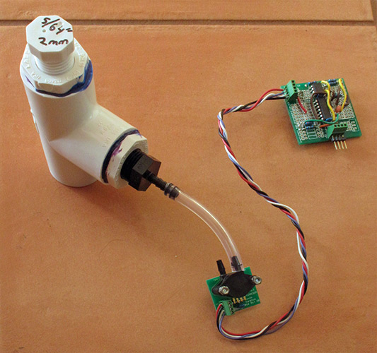
Today, when I went to the hardware store, I did not find any ½” tees with two female threads, so I simplified the design further, eliminating the screw-in plug and just drilling a 5/64″ (2mm) diameter hole into a ½” elbow (one side slip, the other female pipe thread):

The ½" elbow is small enough that I can put my lips around the opening, which would have been a bit difficult with the 1" tee.

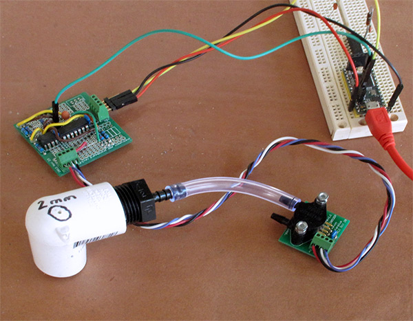
The ½” elbow is small enough that I can put my lips around the opening, which would have been a bit difficult with the 1″ tee.

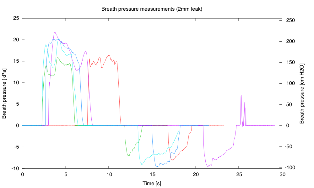
I was able to get similar expiratory breath pressure measurements with either apparatus, but I had trouble getting a good seal for inspiratory measurements with the ½” elbow—I kept getting leaks at the corners of my mouth. None of my measurements today (with either apparatus) got up to the pressures I observed yesterday.  I’ll practice with it a bit more—maybe adding a short length of ½” PVC that I could put a little further into my mouth.  If I can get it to work consistently, it is certainly a cheap enough solution for every student to have their own—79¢ each for the elbows at the hardware store, but only 20¢ from PVC fittings online.

I was not able to figure out where I had bought the 3/16″ barbed fittings from, but I found some for 62¢ each (in 10s) from Cole-Parmer.  At that price, I might even have the students each buy their own, with only the pressure sensors themselves being reused.

2015 September 3

Breath pressure measurements

Filed under: Circuits course — gasstationwithoutpumps @ 18:51
Tags: , ,

I was never very happy with the breath pressure measurements we made in the applied electronics class, because blowing into a little 3/16″ hose did not correspond well with the measurements reported in the literature.  For one thing, the professional measurements are not into a closed tube, but into a small chamber that has a 2mm diameter hole as an air leak. My fix for this last year was to ignore breath pressure and concentrate on blood-pressure cuffs instead, which worked pretty well. But breath pressure should be easy to measure also, so this week I started looking at making cheap apparatus for doing breath pressure properly.

My first attempt just stuck a barbed tee into the hose. Since the opening of the tee is about 2mm, this should give the pressure vs. air flow curve we need.  This cheap approach sort of worked, but I was not able to get very high pressures recorded—much less than what the literature suggests should be average for a man of my age.  I’m pretty sure my lungs are in better than average condition, both for volume and pressure, so I don’t think this simple setup measured breath pressure well. I don’t know whether the problem is the mouth-to-tubing fit, pressure loss along the tubing, or the tee not really behaving like a 2mm orifice—my understanding of fluid flow in tubes and through orifices is rather weak.

In any event, I decided that the solution was to make apparatus that looked more like the equipment shown in the literature.  I happened to have a few barbed fittings with 1/2″ pipe threads, so I went down to the hardware store to get some PVC parts: a 1″ tee, a couple of bushings to reduce the 1″ slip to 1/2″ female threads, and a 1/2″ male-thread plug.  I drilled a 5/64″ hole (2mm) in the plug and assembled my breath-pressure apparatus:

One leg of the tee holds the 2mm air leak, the stem of the tee holds the barbed fitting for connecting to the pressure sensor, and the other leg of the tee is for putting around my mouth.

One leg of the tee holds the 2mm air leak, the stem of the tee holds the barbed fitting for connecting to the pressure sensor, and the other leg of the tee is for putting around my mouth.

The screw-in plugs allow replacing the hole, in case I want to experiment with different size air leaks. The 1″ circle of the tee provides an adequate seal around my mouth, but is not particularly comfortable. The parts cost about $5, so the apparatus is cheap enough.

With this device I managed to get breath pressure measurements comparable to what was reported in the literature, though it took some practice to get high pressures—normal breathing emphasizes high volume, not high pressure.

Plot of high-pressure exhalations followed by high-pressure inhalations (five attempts). I moved the apparatus away from my mouth between breaths, so these are not full breath cycles.  I don't know exactly what the noise at the end of the magenta trace is—probably jostling a loose connection.

Plot of high-pressure exhalations followed by high-pressure inhalations (five attempts). I moved the apparatus away from my mouth between breaths, so these are not full breath cycles. I don’t know exactly what the noise at the end of the magenta trace is—probably jostling a loose connection.

So the breath-pressure apparatus works, but I’ll need to think more about whether to build a dozen of these for the course. There are questions about cleaning the apparatus between users, for example—I don’t want to be spreading cold viruses among my students! Is there a way to make the apparatus more comfortable to use and get a better seal around the mouth.  Commercial peak-flow meters use disposable cardboard or plastic mouthpieces that cost about 35¢ each (in 100s from Amazon), and redesigning the apparatus to use them might be worthwhile—but even then the recommendation is to clean the equipment between users, unless one-way (exhalation-only) mouthpieces are used.  The standard usage (based on pictures on the web) appears to be to have a mouthpiece small enough to go into the mouth, so that the lips seal around it—my current design does not have that.

Perhaps I should try again with just a 1/2″ female threaded tee—that may be cheap enough that every student can have their own, and only the barbed fittings (which get no flow through them) would be shared.  Students wouldn’t even need to buy their own—I could have a stock of 50 of them, and wash them in a dishwasher after the lab.  I’ll have to see how well that works.

2014 June 1

Blood pressure monitor

I thought of a new variant on the pressure sensor lab for the circuits course: a blood pressure monitor.  I happen to have a home blood pressure monitor with a cuff and squeeze bulb that can be detached from the monitor and hooked up to the MPS2053 pressure sensor instead.  With this setup and an instrumentation amp, I can easily record the pressure in the cuff and observe the oscillations in the cuff pressure that are used for oscillometric blood pressure measurement.

Cuff pressure measurements using an MPX2053DP sensor, and instrumentation amp, and a KL25Z microcontroller board running PteroDAQ software.

Cuff pressure measurements using an MPX2053DP sensor, and instrumentation amp, and a KL25Z microcontroller board running PteroDAQ software.

The fluctuations can be observed by removing a baseline (fitting an exponential decay to the dropping pressure, for example, and the subtracting it out) or by using some sort of digital filter. I tried using a 0.3Hz–6Hz bandpass filter (4th order Bessel filter, applied using scipy.signal.filtfilt):

Oscillations corresponding to the pulse are very visible when the slow pressure decay is filtered out.  I've zoomed in on just the time of the dropping pressure, marked with lines on the previous plot.

Oscillations corresponding to the pulse are very visible when the slow pressure decay is filtered out. I’ve zoomed in on just the time of the dropping pressure, marked with lines on the previous plot.

The pulse is very easy to see (about 40.4bpm in this sample—low even for me), but figuring out the systolic and diastolic pressure from the fluctuations is a bit messy:

The oscillometric method of measuring blood pressure with an automated cuff yields valid estimates of mean pressure but questionable estimates of systolic and diastolic pressures. Existing algorithms are sensitive to differences in pulse pressure and artery stiffness. Some are closely guarded trade secrets. Accurate extraction of systolic and diastolic pressures from the envelope of cuff pressure oscillations remains an open problem in biomedical engineering.  
[Charles F Babbs, Oscillometric measurement of systolic and diastolic blood pressures validated in a physiologic mathematical model, BioMedical Engineering OnLine 2012, 11:56 doi:10.1186/1475-925X-11-56 http://www.biomedical-engineering-online.com/content/11/1/56]

One shortcut is to find the maximum amplitude of the envelope of the oscillations, and look at the pressures at fractions of the amplitude:

However, it has been shown that the pressure, Pm, at which the oscillations have the maximum amplitude, Am, is the mean arterial pressure (MAP). Empirical and theoretical work has shown that the systolic and diastolic pressures, Ps and Pd respectively, occur when the amplitudes of oscillation, As and Ad respectively, are a certain fraction of Am:

  • Ps is the pressure above Pm at which As/Am = 0.55
  • Pd is the pressure below Pm at which Ad/Am = 0.85

[Dr. Neil Townsend, Medical Electronics, Michaelmas Term, 2001, http://makezine.com/go/obpm]

I’m too lazy right now to try to come up with a good envelope follower and find the times for 55% and 85% of peak. The peak seems to be around 48.3s in this plot with magnitude of 0.336kPa and a predicted MAP of 16.28kPa (122mm Hg).  I based the MAP on low-pass filtering the signal to remove the fluctuations and make a good smooth curve for finding the systolic and diastolic pressure, once times on the envelope are picked.  Again, a 4th order Bessel filter applied with filtfilt looks good:

Low-pass filtering removes the fluctuations, so that picking two time points can give clean pressure readings for the systolic and diastolic pressure.

Low-pass filtering removes the fluctuations, so that picking two time points can give clean pressure readings for the systolic and diastolic pressure.

From the standpoint of the course, the filtering to get a good signal is probably too difficult, but students could record the cuff pressure and observe the fluctuations. They might even be able to do some crude RC filtering, though this is really an application that calls out for digital filtering.

2012 July 11

Nerf gun analysis, continued

Filed under: Robotics — gasstationwithoutpumps @ 19:04
Tags: , , ,

In Nerf gun analysis, I computed volumes for the reservoirs and made conjectures about why the gun was not working well with the small reservoir and 19 msec pulses.  I had a couple of updates, where I first thought I had gotten the small reservoir working by careful orientation of the solenoid to be pulling with gravity instead of against it.  Then, when my son and I tried together (after he got home from theater rehearsal), that stopped working.  We tried switching to 25 msec pulses, which worked fine with the solenoid horizontal, but again had trouble with the solenoid vertical.

We did do a series of pressure measurements for the system with the 25 msec pulses:

Pressure drop per pulse for the system with small reservoir connected to the large reservoir by an air hose, firing with no dart in the barrel. Once again we see a linear pressure drop, indicating that a constant mass of air is moved in each pulse, independent of pressure.  This series is cleaner than the previous one, because the gauge on the pump was read close up always from the same position, reducing parallax errors.

Given the volume of the reservoirs, we can again compute the amount of air moved on each pulse:

component length (cm) diameter (cm) volume (mL)
barrel  68.5  1.5  121
reservoir  48.5  4  609.5
mini-reservoir  21  2  66
air hose  762  0.6  215.5

The total volume behind the valve is about 891 mL, and a pressure drop of 2.24 psi is 0.152 atm.  Using a density of 1.225 mg/mL at 1 atm, we have  about 166 mg of air being released on each pulse: a little more than before.

The gun seemed reliable with 25 msec pulses when the solenoid was horizontal, but still had problems when the solenoid was working against gravity, so perhaps we need pulses that are longer still—say 30 msec. We tried 30 msec and it seemed to fire ok even with the solenoid working against gravity.  We did a series of pressure readings  with the 30 msec pulses also:

Series of blank fires with 30 msec pulses with the solenoid horizontal. We are now releasing about 2.49 psi  * 0.06806 atm/psi * 891 mL * 1.225 mg/(mL atm) or 185 mg of air per firing (150 mL at standard pressure).

We should probably do another series with the solenoid working against gravity, so see if we can see a smaller air release in that orientation.

I did get the microphone setup working, and I could see that the air blast out of the barrel was starting about 5–10 msec after a 19 msec solenoid pulse was finished, which is much slower than it would take the air to travel that far.  The delay was smaller at lower pressure, so I suspect that what we are seeing is mechanical delay in the movement of the valve.  I’ll look at it again with the longer pulses, to see if the air blast now comes out while the solenoid is still powered.  It is a bit difficult to see the pulses, since we are looking a  single shot on an old analog scope, not captured by a digital storage scope.  Perhaps tonight when it gets dark I can try taking some long-duration photos and capturing the scan.