Gas station without pumps

2020 March 25

Grading done

Filed under: Circuits course — gasstationwithoutpumps @ 21:26
Tags: , ,

I’ve finally finished my grading for Winter 2020.  It took me longer than usual—about 2 hours per paper.  Partly this was because I had some trouble focusing on work with all the COVID-19 news, partly it was because I kept getting distracted by undergrad-director duties (cancelling lab courses for next quarter and trying to get two additional courses funded and staffed with TAs), and partly it was an attempt to give the students more thorough feedback than usual, because some of them will not be taking the second half of the course.

We decided that any student who is graduating in Spring 2020 can petition to replace a cancelled lab course (like the second half of my course) with a different course that they can take (or have taken).  Reading those petitions has been one of the undergrad-director duties that has been taking up my time.  So far, most of the petitions have been acceptable—students have given pedagogic justifications for their choices that made the substitutions reasonable, even if not covering the skills that the cancelled course would have taught.  In a few cases, I’ve suggested that students revise their petitions, particularly when they’ve proposed replacing a 5-unit course with a 3-unit one.

I also ended up letting 17 of the 50 students in my course switch from graded to pass/no-pass, which is not usually something faculty can offer. Because Winter 2020 was such a disaster at UCSC (between the wildcat strike and the COVID-19 shutdown), faculty are allowed to assign P/NP grades this quarter, even if students didn’t sign up for them.  The programs in the Baskin School of Engineering usually require that all courses in the major be taken for a grade, but the BENG/BINF/BMEB majors are being allowed to have P/NP grades for Fall 2019 and Winter 2020 even in major courses.  I let the students choose whether they wanted the grade they earned or a P/NP for my course, though they only had about 3 hours to make up their minds.

The grades were lower than usual this quarter, even after I lowered the cutoffs for each grade.  Because the quarter was so stressful for students, I lowered the cutoffs much more than I usually would have.  This may come back to bite me in the fall, as there were three students who were not really doing passing work (should have gotten C-), who I passed anyway.  If they have the same sloppy approach to their work in the Fall, they will not pass BME 51B, causing their lab partners and me a lot of grief in the process.

In some ways the reports this year were better than previous years—there were fewer incorrect symbols for the NPN phototransistor and the bandpass filters were generally ok. But in some ways they were worse—there were only a few students who understood what the log-transimpedance amplifier did and reported its gain correctly, and there were many who had inconsistent component values in different schematics or between the schematic and the main body of the report. A lot of students keep making the same mistakes in report after report—apparently they never read the feedback I spend hours giving them or ignore it as unrelated to anything they do.

The writing quality remains mostly bad—though perhaps that is not so unusual for this point of the course—I think that the second quarter of the course is when most of the students begin to pay attention to the writing feedback and working on improving their writing.  There were a few students whose writing was ok on the Lab 6 reports, though nothing extraordinarily good.

One thing I’ve noticed every year in the pulse-monitor lab is that a lot of students attribute the 60Hz noise to the fluorescent lighting or to electromagnetic interference, rather than capacitive coupling. But no one has done any tests to see which was the true source. I should do some tests (black out the phototransistor with electrical tape, but keep my finger on it vs. expose phototransistor to fluorescent light with no capacitive source nearby, contrast the fluorescent light to steady light, …).

One problem will be finding old-fashioned 60Hz fluorescent lights at home—I don’t know that we have any left, as I’ve replaced all the oldest fixtures with LED lights. We still have some compact fluorescent bulbs, but they generally have high-frequency electronic ballasts to avoid the 60Hz flicker.I might have to sneak into my office at work to do the tests, if all the lights at home have higher-frequency modulation.

I may also have to do tests with a normal transimpedance amplifier, rather than a logarithmic one, as I want to see the fluctuating current added to the DC light value, rather than looking at ratios of current as we do for looking at the opacity of the finger. A fixed additional current would result in very different voltage fluctuations with different DC light levels, if I used the log-transimpedance amplifier.

2017 November 17

Tape sensors

Filed under: Robotics — gasstationwithoutpumps @ 15:06
Tags: , , , ,

One of the requirements of the robot for Mechatronics is that it have optical sensors on the bottom to detect black tape on a white background, for detecting the edges of the field, alignment marks for the Ren-ship target, and other marks on the field that seem to be there just to be a nuisance and make the state-machine design harder.

We were issued a number of TCRT5000L reflective sensors, which consist of an IR emitter and a phototransistor in a plastic package that is optimized for a surface 2mm away.  Although the sensors are designed to snap into PC boards and could probably be snapped into carefully sized holes in MDF, I’ll be mounting them on perfboards, which will be screwed onto the top of the baseplate of my robot, with rectangular holes in the MDF for the sensor to poke through.  They’ll barely poke through (6mm high — 5mm MDF), which means they’ll be about 7mm from the floor.  At that distance, the collector current is about half what it would be at the optimum distance.  The MDF provides some extra shrouding from stray light from the sides, which should help with detection.

I’m planning to turn the IR emitters on only when I need to read the sensors, to save power and to allow synchronous detection of reflectance (looking at the difference in light levels between the IR emitter being on or off).  By keeping the duty cycle below 50%, I can run the IR emitters up to 50mA, though I may not need them to be that bright.

If I switch on 5 IR emitters at once, at 50mA each, I’ll be  using 250mA, which is the limit for what I could get from the Teensy 3.2 3.3V regulator (rated for 250mA, though that’s a thermal limit, so 500mA may be available for low duty cycle) and far exceeds the 100mA limit for Teensy LC or Teensy 3.1 boards.  I will be using a 5V regulator to power the Teensy boards, so I could use the 5V supply to power the IR emitters also.

If I use only 10mA per IR emitter, I only need 50mA total and so could power off of either 3.3V or 5V.

For 50mA at 5V, I’d need a current-limiting resistor of ≥(5V–1.2V)/50mA=76Ω, so an 82Ω resistor for 46–48mA would work.  For 10mA at 5V, I’d need ≥(5V–1.1V)/10mA=390Ω, and for 10mA at 3.3V, I’d need ≥(3.3V–1.1V)/10mA=220Ω.

I have a couple of choices for wiring up the sensors:

There are 3 wires to each sensor board, but only the current output is unique to the board—the IR emitter connections can be shared among all sensors.

Low-side switching only requires an nFET, but the power connection for the IR emitter is limited to 3.3V. High-side switching keeps the 3.3V power line from being routed near the motors, but requires a 5v-powered inverter to get a sufficiently large voltage to shut off the pFET.

The expected current from a white background @7mm is about 400µA for 10mA input or 2mA for 50mA input, assuming VCE is in the active region (above about 0.5V).  If I’m looking for a 1V swing between dark and light, I’ll want about 2.5kΩ for the sense resistor for a 10mA input and 500Ω for a 50mA input.

I did a couple of tests with the TCRT5000L using the low-side switching configuration, with 3.3V and a 220Ω current-limiting resistor.  I was doing the tests in a well-lit room (my breakfast room on a sunny day, but without direct sunlight in the room), so the background light is probably brighter than the robot will ever have to deal with.  I used one of the wheels from the MockRobot to be the target, since I could put a screw through the axle hole to get a more-or-less consistent spacing from the sensor.  I adjusted the nut so that the spacing was about 7mm from the sensor, but the angle was only controlled by eyeballing the levelness of the target, so probably varied by ±10°. I did not have any of the black tape that was used on the fields, so I substituted black electrical tape, which I think may be slightly more reflective.

I initially tried 2.7kΩ as the sense resistor, but after seeing the voltage range for that, I upped it to 5.1kΩ.

With 5.1kΩ, the voltages when illuminated are very different between black and white—a simple digital input would suffice.

The currents can be seen to be about the same, independent of the sense resistor, with the white MDF giving about 10 times current of the black electrical tape. The signal from background illumination is insignificant, though that might not be true if the IR beacon is lighting up the field.

It looks like 10mA (measured as 9.65mA) is more than enough light for the sensors to tell black from white, and that the signal is strong enough that I don’t really need analog input or synchronous sensing for the tape sensors.  If I get really worried about the digital signal in worst-case conditions (like too large a distance), I could increase the size of the sense resistor further.  With a 22kΩ sense resistor, I get a very clean separation between white and black even at 1cm.

I have to decide whether to pulse the IR emitters and wait at least 100µs before reading all the sensors, or just to leave them on all the time (at a cost of 10mA per tape sensor). If they are on all the time, I could use the 5V supply (with a 390Ω current-limiting resistor instead of a 220Ω one), and not worry about overloading the Teensy regulator. This could also simplify wiring, as the 5V regulator could be on the power board on the first level and the battery wiring would be limited to the first level.

The Teensy 3.1/3.2 digital pins are 5V-tolerant, so I could even connect the phototransistor collectors to 5V and put the multiplexer on the first level using 5V power. I could then put the sense resistors on the tape-sensor boards and have three wires for each board: 5V, GND, and WHITE.  I could use 3-pin male headers and standard Futaba servo cables to do the wiring.

I ordered a set of servo cables through Amazon, but they are not expected to arrive for another 2–6 weeks, so aren’t going to do me much good.)  I can make my own, but I’ve been having trouble lately with intermittent contacts from the crimp-on connectors and have taken to wicking tiny amounts of solder into the crimp, which adds a lot of time to making the cables.

With the multiplexer on the first layer, the only cabling from the tape sensors to higher levels would be 5V, Gnd, 3 select signals, and the (now digital) signal for sensing the tape. The motors are also on the bottom level, and they would additionally need 2 wires for controlling each motor and 2 wires per motor for feedback from the Hall-effect encoders. This makes the total wire bundle from the bottom level up to higher levels be only 14 wires (5V, Gnd, 4 for tape sensors, 2×4 for motors), with none of the wires having high-current switching.  The only high current wires are the 5V and Gnd wires, which may be feeding servo motors on higher levels—I may want a separate power wire from one of the switching regulators for powering servo motors on the higher levels, though.

The Teensy LC is not 5V-tolerant, so if I used that for the main controller board, I would need to communicate a 3.3V power line as well for the phototransistors and the motor encoders.  I think that I’ll simply declare that the main controller needs to be 5V-tolerant for digital inputs.

[Update 2017 Nov 18: I soldered up one of the TCRT5000L circuits, so that I could do a little more testing and make sure that I had a layout that worked.  It turned out that 22kΩ for the sense resistor was too large—at some distances the electrical tape reflected enough light to get above the 1.15V which is the guaranteed max VIL and maybe even enough to get to switch to high. I took out the 22kΩ and used a 10kΩ, and the problem with black reflecting too much light went away, but white still produced a very strong signal. I should be able to detect the white board reliably with just digital inputs out to about 1.4cm, much more than the 0.8cm clearance.

2017 April 29

Santa Cruz Mini Maker Faire 2017

Today I spent about 10 hours on the 2017 Santa Cruz Mini Maker Faire.  The hours for the Faire were 10–5, but I spent some time setting up and tearing down afterwards, so I left the house around 8:30 a.m. and had the bike trailer unpacked and everything back in the house by about 6:30 p.m.  I figure that I spent only about 10 hours earlier on setup for this Faire: applying for the Faire, setting out all the displays and testing them at home, preparing new blurbs for my book and blog, making table signs telling people how to use the interactive parts of the display, blogging about the Faire, and doing load-in last night.  That is a lot less than last year, as I was able to reuse a lot of the design from last year.

Here is the table display I ended up with:

The bare corner at the front left was reserved for the students in my freshman design course who were coming to display their muscle-controlled robot arm, but they decided to set up in back (you can see one of the lead students in the background).

I had four interactive displays (from left to right):

  • A pair of function generators and an oscilloscope showing Lissajous figures.  I changed this from last year, as I did not use the FG085 function generator this year, but one of the function generators from the Analog Discovery 2.  I still used the Elenco FG500, despite the very low quality of its waveforms, because it has a knob that is easy for kids to turn, and is easy to reset if they mess it up (unlike the jamming buttons on the FG085).  I did not use the second function generator on the Analog Discovery 2, as I did not want kids playing with just a software interface (and a rather complicated one at that).  It might even be worthwhile for me to build a simple audio sine-wave oscillator with a single big knob over the summer, so that I can have something for kids to play with that is fairly robust and that can’t be easily set into a weird state.  I could even do two, just for Lissajous figures, though having one fixed oscillator worked well this time.  I had the Analog Discovery 2 oscilloscope showing on the laptop next to the old Kikusui CRT oscilloscope, showing both the waveforms and the XY plot, so that I could explain to adults what was happening with the Lissajous figures and about the differences between classic oscilloscopes and modern USB-based ones.
    A lot of people asked me about the Analog Discovery 2, which I was very enthusiastic about—Digilent should be giving me a commission! (They aren’t, although I’m sure I’m responsible for at least half a dozen sales for them, and a lot more if we go ahead with our plan to use them in place of bench equipment in my class next year.)
  • In front of the laptop showing the Lissajous figures, I had a standalone optical pulse monitor using the log-transimpedance amplifier and the TFT LCD display.  Using the log-transimpedance amplifier worked well, as did using a lego brick to block light to the sides and back of the phototransistor.  A lot of people have trouble holding their hands still enough to get good readings (particularly children), so it would be good to have some sort of clip instead of resting a finger over the phototransistor.  I’ve tried making clips in the past, but I’m not good at mechanical design, and I’ve always ended up with either a clamp that is too tight (cutting off circulation and getting no reading) or too loose (falling off).  Ideally, I’d want a pressure between systolic and diastolic pressure, so about 12kPa (90mmHg).  People did like the use of Lego as a support, though—it provided a familiar element in the strange world of electronics.
  • To the right of the pulse monitor was a pressure sensor.  I had a mechanical gauge and the electronic sensor both connected to a piece of soft silicone tubing taped to the table top.  Kids pressed on the tubing to get an increase in pressure, visible on the gauge (about 20–60 mmHg) and on graph PteroDAQ was running on the little laptop (which we refer to as the “Barbie” laptop, because of its color and small size).  I explained to kids that the tubing was like the tubing stretched across roads sometimes to count cars, with a pressure sensor that recorded each pulse as wheels compressed the tubing.  (For some of the old-timers, I reminded them of when gas stations used to use a similar system.)
    PteroDAQ worked well for this setup, running all day at 20 samples per second without a glitch.  The only problem was occasional display sleep from the laptop, fixable by touching the touch pad.
  • At the far right end of the table, I had a phototransistor which kids could shadow with their hands, with the result visible on another channel on PteroDAQ.  This was a last-minute change, as I was getting very unreliable results from the capacitive touch sensor when I tested it out last night.  The capacitive touch sensor worked fine at my house, but in the kindergarten room at Gateway I has a different electrical environment, and it would not work unless I grounded myself. Rather than fuss with the touch sensor, I made a new table sign and put in a light sensor instead.
    I might want to experiment this summer with different ways of making touch plates—trying to get one that doesn’t rely on the toucher being grounded.  My initial thought is that if I have two conductors that are not too close together, but which would both be close to a finger if the touch plate is touched, then I may be able to get more reliable sensing.  I could try some wire-and-tape prototypes and maybe make PC boards with different conductor layouts.  (OSH Park‘s pricing scheme would be good for such tiny boards).

I also had my laptop displaying my book; some quarter-page blurbs with URLs for my book, PteroDAQ, and this blog; my 20-LED strobe; my desk lamp; and a PanaVise displaying one of the amplifier prototyping boards.

I’d like to think of a more exciting project for kids to play with next year—perhaps something I could build over the summer.  Readers, any suggestions?

In addition to my display, some of the freshmen from my freshman design seminar class demonstrated their EMG-controlled robot arm (which uses the MeArm kit):

The students built a MeArm from a kit, then programmed a Teensy board to respond to muscle signals amplified by amplifiers designed by other students in the class. The combined project had two channels: one for controlling the forward-backward position of the arm (using the biceps), the other for controlling the gripper (using muscles in the forearm). With practice, people could pick up a light object with the robot arm.

The scheduling of the Mini Maker Faire was not ideal this year, as it conflicted with the Tech Challenge, Santa Cruz County Math contest, the California Invention Convention, and the Gem and Mineral Show, all of which draw from the same audience as the Mini Maker Faire.

The Faire seemed to be reasonably well attended (rather slow for the first hour and half, but picking up considerably in the afternoon).  There was plenty of room for more exhibitors, so I think that organizers need to do a bit more outreach to encourage people to apply.  It would probably help if they were quicker responding to applicants (it took them over three months to respond to my application, and then only after I nudged them).

Some obvious holes in the lineup: The Museum of Art and History did not have a display, but I saw Nina Simons there, and she said that MAH definitely plans to do it next year, but the Abbott Square renovation is taking up all their time this year.   The fashionTEENS fashion show was April 21, just over a week ago, so it would have been good to get some of them to show their fashions again: either on mannequins or as a mini-show on the stage.  It might be good to get some of Santa Cruz’s luthiers or fine woodworkers to show—we have a lot of top-notch ones, and many do show stuff at Open Studios. The only displays from UCSC were mine and the Formula Slug electric race car team.

Of the local fab labs, Cabrillo College Fab Lab and Idea Fab Labs were present, but The Fábrica and the Bike Church were not.  I thought that Cabrillo did a great job of exhibiting, but Idea Fab Labs was a little too static—only the sand table was interactive.

It might be good to have Zun Zun present their Basura Batucada show (entirely on instruments made from recycled materials) and have a booth on making such instruments.  It might be hard to get Zun Zun to volunteer, but they used to be very cheap to hire (I hired them to give a show at my son’s kindergarten class 15 years ago—they were very cheap then, but I don’t know what their prices are now).

One problem my wife noted was the lack of signs on the outside of classrooms, so that people would know what was inside.  The tiny signs that the Faire provided (I think—I didn’t get one) were too small to be of any use.  It may be enough to tell makers to bring a poster-sized sign to mount.  I had my cloth banner behind my table, but a lot of the displays were hard to identify.  Instructions or information mounted on tables would also have been good—again these would have to be provided by the makers.  I did not see people carrying maps this year—they can also be helpful in getting people to find things that were tucked away in odd corners.  Not many people made it back to the second kindergarten room where FabMo and the Lace Museum activities were.

Update 2017 May 1: It turns out that there were some things I missed at the Faire.  The principal of Gateway sent me email:

… we did have 4 of the Fashion Teens exhibit their creations on the stage at 11:30—might be cool to have them put those on mannequins and have a booth next year. Also we had two more UCSC projects—Jim Whitehead and the Generative Art Studio, and Project AWEsome from the School of Engineering. We would LOVE to have more UCSC-related projects …


2016 June 25

Pulse monitor with log-transimpedance amplifier

Filed under: Uncategorized — gasstationwithoutpumps @ 02:04
Tags: , , , ,

I’ve been planning since the Santa Cruz Mini Maker Faire to wire up an optical pulse monitor with a log-transimpedance amplifier as the first stage, so that I could use the pulse monitor in full sun or in a dimly lit room, with a dim green LED or with a bright infrared LED. The idea is to make the output of the first stage proportional to the log of the photocurrent, rather than to the photocurrent, then use a band-pass filter to get rid of the DC component and any 60Hz fluctuation, leaving only the fluctuation due to the pulse.

This pulse signal should be independent of the overall light level but on the absorbance of the finger, because
\log(I) = c + \log(\mbox{transmitted}) = c+ \log(\mbox{illumination}) + \log(\mbox{transmitted}/\mbox{illumination}, for some constant c. If the illumination is constant or has only high-frequency components, then the bandpass filter will eliminate both c and \log(\mbox{illumination}), leaving only the absorbance \log(\mbox{transmitted}/\mbox{illumination}).

I deliberately did not start working on it until I had finished my grading for the quarter, so only got it built last week, just before going to Montreal for a family reunion of my wife’s family. So I’m only now getting around to blogging about it.

To make the log-transimpedance amplifier, I need a component where the voltage is proportional to the log of the current.  For this I used a diode-connected PNP transistor:

The base-to-emitter diode has a current that is exponential in the voltage, and the collector-to-emitter current is proportional to the base-to-emitter current, at least until the transistor approaches saturation (which starts around 10mA).

The base-to-emitter diode has a current that is exponential in the voltage, and the collector-to-emitter current is proportional to the base-to-emitter current, at least until the transistor approaches saturation (which starts around 10mA).

The A1015 PNP transistor has a voltage proportional to the log of current, with about 60mV/decade. I did not use a unity-gain buffer when measuring the voltage and current, connecting the Teensy ADC channels A10 and A11 directly to the emitter and base+collector of the transistor. Measurements at less than 5µA were difficult, because the high impedance of the sense resistor made the ADC measurements inaccurate.

I tried a pulse monitor using the A1015 PNP transistor as the log-impedance element, and it worked ok, but I can do better, I think, using an IR LED as the log-impedance element:

The WP710A10F3C IR LED has a low forward voltage, and can be used from 100nA to 30mA, given that we don't need high accuracy on the log function. We get about 105mV/decade, so it is more sensitive than the A1015 transistor.

The WP710A10F3C IR LED has a low forward voltage, and can be used from 100nA to 30mA, given that we don’t need high accuracy on the log function. We get about 105mV/decade, so it is more sensitive than the A1015 transistor. Note: I did use a unity-gain butter for these measurements, which allowed me to get down to about 50nA—still much higher than the photocurrents I observed in very low light.

The IR LED has a wide range over which the voltage is the logarithm of the current, or \frac{dV}{dI} \approx 241mV/I
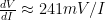
. For 10nA, the equivalent gain is about 24MΩ, and for 1µA, the gain is about 240kΩ. For 10pA (about the smallest current I’ve observed for operating the pulse monitor in very dim light), the equivalent gain is 24GΩ.

This amplifier uses only 3 op amps: a log-transimpedance stage with an IR LED as the impedance, and two bandpass inverting amplifiers.

This amplifier uses only 3 op amps: a log-transimpedance stage with an IR LED as the impedance and two bandpass inverting amplifiers.

The 330pF capacitor in parallel with the log-impedance is very important—without it I get very short glitches which the next two stages lengthen into long glitches in the passband of the filters.  Making the capacitor larger reduces the glitches, but makes the corner frequency of the effective low-pass filter too low when light levels are very low, and the signal is attenuated.  Any smaller, and the glitches don’t get adequately removed.

I have tested the pulse monitor over a wide range of light levels, with a DC output of the first stage from 234mV to 1.033V, corresponding to photocurrents of 11pA to 463µA, a range of 42 million (7.6 decades). At very low light levels, the signal tends to be buried in 60Hz interference, but if I ground myself, it is still usable.

In very low light, the capacitive coupling of 60Hz noise buries the signal, but the bandpass filters help recover it.

In very low light, the capacitive coupling of 60Hz noise buries the signal, but the bandpass filters help recover it.

At high light levels, it is easy to get clean signals, as the 60Hz interference is swamped out by the large photocurrent.

At high light levels, it is easy to get clean signals, as the 60Hz interference is swamped out by the large photocurrent.

Note that the voltage swing is almost independent of the overall light level, as it depends only on the percentage fluctuation in opacity of the finger, which depends mainly on how much pressure is applied. If you get the pressure on the finger close to the mean arterial pressure (so that the finger throbs), you can get quite a large change in opacity—I’ve computed changes of 17% in opacity.

2016 May 11

Don’t put pulse monitor first

Filed under: Circuits course — gasstationwithoutpumps @ 21:25
Tags: , , ,

In Revised microphone pre-amp lab too long I said,

I think that the soldering lab should not be the first op-amp lab, but I still like the idea of the students having to solder up their microphone preamps. So I’ll have to do a major reorganization of the book this summer, to move a different lab into the first position.

Currently, I’m thinking that the transimpedance amplifier and pulse monitor lab would be a good choice as the first op-amp lab.

After a rather rough start in the first half of the transimpedance-amplifier lab yesterday, I no longer think that is a good idea. The instrumentation-amp lab went much smoother, so may be a better first choice.  Among other advantages, the instrumentation-amp lab with the pressure sensors has no analog filtering and simpler sensor sensitivity calculations.  One disadvantage of moving away from the mic preamp is that the microphone and loudspeaker characterization in the first half of the class would be separated from the audio amplifier design in the second half—not a problem in a single quarter class, but potentially a bigger problem in a two-quarter sequence.

I’m not sure why the transimpedance amplifier lab went poorly yesterday, and I’m hoping the second half will go smoother tomorrow.  It may be that prelab was not a good match for the lab this time.  Or it may be that over a third of the class didn’t do the prelab this time.  (I’ve threatened the class with a quiz worth as much as a design report if they don’t shape up by next week—I’m carrying around enough redone reports to grade that I really don’t want to do more grading, but I’ll follow through on the threat if so many students continue slacking.)

It turns out that I had several errors in the draft of the book that the students were using for the prelab exercises for the optical pulse monitor.  I’d decided in the summer or fall to switch to a new 700nm LED, but I’d only updated about half the scaffolding for the sensor sensitivity, so there were still a number of things that were only accurate for a 623nm LED.  Also, I’d been using a datasheet for the WP3DP3BT that I’d gotten when I first started using the part, but Kingbright has improved their datasheet a lot between V3 (which I had) and V5 (the current one), so there is now a spectral sensitivity curve on the datasheet, and the spectral sensitivity is quite different from what I was expecting.

I’ve started editing the book to correct the errors, but even after I fixed everything, the estimates for the current from the phototransistor were about 5% of what students were measuring in the lab. The model I had created, which worked fairly well for the previous LEDs, does not seem to work for the longer wavelength of the new LED.

I’m considering simplifying the model by eliminating the modeling of scattering, to see how well that works.  I should check the model with at least 3 different LEDs: the current 700nm one, the shorter wavelength ones I used to use, and an IR emitter.  If I can get the estimates to be within a factor of 10 of measured values for all the LEDs I have, then the model is good enough to include in the book.

I might also want to consider switching phototransistors to one with a wider spectral sensitivity, so that the estimation is not thrown off as much by the filter that blocks so much of visible light.  That would allow me to try a green LED as well.

I’m still thinking about doing a log-transimpedance amplifier as the first stage (not for the class, just for a demo unit) so that the pulse monitor can work in varying light levels up to full sunlight.  The fluctuation in light from the pulse seems to be about 1%, which should be a variation of about 850µV out of the logarithmic amplifier (based on the 9.8mV/dB I measured in Logarithmic amplifier again).  That’s a somewhat smaller signal than I’ve been getting with well-chosen gain resistors, but it may be worth it to get greater independence from the overall light level.

Next Page »