Gas station without pumps

2015 December 27

Theater lights

Filed under: Uncategorized — gasstationwithoutpumps @ 00:02
Tags: , , , ,

My son and I have started on his summer project while he is home for winter break—to build a moderately bright, adjustable color theater light for WEST Performing Arts, the children’s theater troupe he has worked with for the past 11 years (including the two years before they split off from Pisces Moon).

The design is still very much in flux (we’re on our third processor choice already), and we haven’t done any parts ordering or physical prototyping yet, just thinking about circuits, parts, and layout.  We are currently planning an RGBW light with DMX control, with 20W each of red, green, and blue LEDs, and 40W of warm white LEDs, all mounted in a PAR-38 can (using an old can from WEST, rather than buying a new can).  The light will be a simple flood, which is easier to construct than a fresnel or spot light, because we don’t have to concentrate all the light into a small spot for manipulating with lenses.  Currently WEST uses 75W or 100W incandescent bulbs in their PAR cans, so the LED light should be three or four times brighter.  There are RGBW lights from China that are about the same brightness as we’re aiming for, but they are larger and more expensive—we’re aiming for a budget of about $100 a light for parts.  (We’d not be able to sell them any cheaper than the commercial lights—this is just a hobby project to make one or two lights for the theater.)

The theater has a few 15W RGB lights with DMX control, the American DJ Mega Tripar Profile, but they are only 5W per channel (not really bright enough) and it is not clear what functionality the DMX controller for them has (we didn’t look at it or find out the model number).  Because the set was a very cheap lighting set, it probably can’t handle the greater functionality we’re planned for the RGBW lights, so we’ll probably have to find or design a simple DMX controller that can be run from a Mac laptop. There are some open-source DMX controller projects on the web, but their user interfaces may be a bit too complicated for the kids (or non-techy staff) running the light booth for WEST. It is not clear whether we can design a simpler interface for a small number of lights that provides easy access to all the functionality of the lights.  There is also the question whether a traditional control board with sliders or an all-virtual laptop-based controller is a better interface for beginning lighting techs.

We might even want to look at an iPad-based controller, like Luminair ($90), LightingPad (discontinued), and RunTheShow (free, but limited to controlling their particular hardware). LightingPad says that they have pulled the product until they can update for iOS8, which was released over a year ago—since iOS9 has come out before they updated to iOS8, it seems unlikely that they will ever be able to keep up with the churn in the iPads (a complaint I’ve heard from other iPad app developers—Apple makes it very difficult for older apps to keep running, requiring a full-time developer just to keep up with Apple breaking things on each release).  Hmm, I seem to have talked myself out of developing an iPad app, but we probably should make sure our hardware can run with controllers like Luminair.

For laptops, there are open-source projects like Elios and WhiteCat.  Elios is an open-source project in Java, but it hasn’t been updated for a couple of years, so may be a dead project.  WhiteCat seems rather complicated, based on the screenshots at http://www.le-chat-noir-numerique.fr/index_eng.html, and most of the documentation is in French, which neither my son nor I reads.

Since we’re mainly interested in running on MacBooks, the OS-X-only code from LightKey may be usable.  They have a free version with 24 channels that might be usable, though upgrading to more channels gets into an expensive subscription model.

The controls we are planning for the RGBW light were 16-bit PWM on each of the 4 channels, plus a strobe frequency (in units of 0.1Hz, with 0–5 and 250–255 having special meanings—probably always off and always on).  Because the DMX512 protocol only has one byte per channel, the light would need 9 channels, and the free version of LightKey could only control 2 such lights.

The Tripar Profiles can be configured as anywhere from 1 to 7 channels:

  1. choice of 16 preset colors (“color macros”);
  2. 16 colors plus 1-byte dimmer;
  3. RGB;
  4. RGB plus master dimmer;
  5. RGB, dimmer, color macros;
  6. RGB, color macros, strobing, master dimmer;
  7. RGB, color macros, strobe or program speed, preset programs, master dimmer.

The preset programs are mainly for running the light as a standalone light show without a DMX controller, so we would not want to emulate that.  The 4-channel RGB,dimmer function is intended as a workaround for the low resolution of 8-bit PWM control—you pick the color at full brightness, then multiply by the dimmer setting to get the overall effect.  Since we are planning to use 16-bit PWM, we can get more precise color control even at dim light settings.  If we mix our light with the Tripar Profiles, we would probably use the Tripar Profiles in 4-channel mode (unless we needed strobing, in which case we’d use 6-channel mode).

I mentioned above that we’d been through three different processor choices.  At first we thought of using a Teensy board, because we’re familiar with ARM programming, the Teensy boards are easy to program, and they can be treated like a through-hole part for doing prototyping (by adding some header pins).  But the boards are a bit large, and a bit expensive ($11.65 for a Teensy LC), so we next considered using an ATtiny2313A processor (again, the ATtiny is easily programmed and I have some experience with the ATtiny13, which I used for the PWM on my desk lamps).  Unfortunately, the ATtiny2313A provides only 2 16-bit PWM channels (plus 2 8-bit channels), which is not really adequate.  Using two ATtiny2313A chips would work, but for less money and less board real estate, we can use a PIC32MX110F016B-I/SP and get 16-bit PWM on a 40MHz clock for a 610.4Hz PWM frequency.  The flexibility of the pin remapping on the PIC32 is attractive here, as it can simplify the routing of the board.

The processor not only has to interpret the DMX commands and provide PWM outputs, it also has to support the RDM (remote data management) protocol of modern DMX devices (the Tripar Profiles don’t, but there is no real excuse for not supporting RDM these days).

Here is a rough block diagram of the current design:

Each LED here is nominally a 10W LED module.

Each LED here is nominally a 10W LED module.

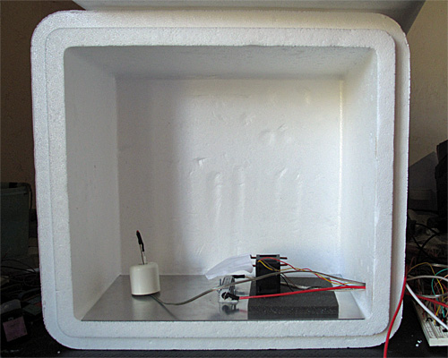
We’ve given some thought to the heat sink, fan, and mounting brackets for everything, but there is still more work to be done to make sure that we can really dump all the waste heat and keep the LEDs sufficiently cool.  We’re currently looking at about $80 in parts for the light (not including the can, which we’ll get from WEST) plus another $15 to make a USB-DMX interface that can handle the RDM protocol.  Those numbers may change a fair amount as we play with the design.

The two boards are each about 10cm by 5cm, which cost only $12 (for 10 copies) from Smartprototyping.  My son has done preliminary layouts of them, to see how big the boards would be and determine any mechanical problems we might encounter.

2015 November 5

Book draft 2015 Nov 5

Filed under: Circuits course — gasstationwithoutpumps @ 22:39
Tags: , , , , ,

I released an updated version of the Applied Electronics for Bioengineers text today.  This draft involved several changes:

  • Added modifier for “resistor” at end of Section 5.1
  • Changed “load resistor” to “bias resistor” in microphone chapter and lab.
  • Fixed microphone schematics to use polarized microphones.
  • Figure 11.2 changed to use only one differential channel on PteroDAQ.
  • Brief explanation of RMS added to Section 3.2
  • Small fixes to Chapters 9–16 and indexing terms added.
  • Index cleaned up.
  • 60Hz FM figure added to Chapter 14
  • Updated power discussion in Sections 0.5, 12.3, 23.1
  • Updated to include Teensy 3.2
  • Major rewrite of Chapter 23 (Class D power amp)

I’m still not finished with the Class D chapter, but I managed to test today an H-bridge circuit using a 9V power supply, which could provide ±9v signals to a loudspeaker (the full 10W that the loudspeaker can take).  I did not actually drive the loudspeaker that far, but I confirmed that the H-bridge was providing the full voltage range for PWM and that I was getting clean signals at the loudspeaker for loudness I was willing to tolerate listening to.

I’m now convinced that an H-bridge design is a simpler approach to teach the students, as well as being more useful for students who go on into the “assistive technology: motor” concentration.  Modifying the H-bridge to use logic-level signals from the comparator but high voltages for the power FETs turned out to be quite simple.  I just added a small nFET and a couple of resistors to make an inverter with a small voltage swing on the output:

Q1 and the resistors R1 and R2 form an inverter for driving the pFET.  Sizing R1 and R2 determines the voltage swing on the pFET gate  (Q2) and how fast the turn on and turn off are.  Of course, when Q3 is on, there is a current through it that is wasted (not delivered to the load), but I was able to keep that down to about 15mA.

Q1 and the resistors R1 and R2 form an inverter for driving the pFET. Sizing R1 and R2 determines the voltage swing on the pFET gate (Q2) and how fast the turn on and turn off are. Of course, when Q3 is on, there is a current through it that is wasted (not delivered to the load), but I was able to keep that down to about 15mA.

2015 September 17

H-bridge Class-D hum problem solved

Filed under: Circuits course — gasstationwithoutpumps @ 17:12
Tags: , , , ,

I H-bridge Class-D works I mentioned

I was getting a rather annoying amount of 60Hz hum, probably from the microphone preamplifier.  I’ll have to play with it a bit tomorrow to see if I can avoid the hum pickup.


It turned out to be a fairly simple, but unexpected problem.  The TLC3702 comparator chip has 2 comparators in the package, and I had not connected anything to the second comparator.  Connecting the inputs to ground eliminated the hum!  I think that what was happening was that 60Hz pickup on the unconnected input was causing the second comparator to swing back and forth at about 60Hz, and that this was coupled internally to the comparator I was using (probably through the shared power connections). By silencing the second comparator, I removed this source of hum.

My son also noticed a high-pitched noise that was barely audible to me.  I figured that the source was probably the low-quality triangle wave from the FG085 function generator. If the period is not an exact multiple of 250ns, then the sampling of the triangle wave gradually shifts phase, and that changing phase turns into a PWM signal that is audible on the speaker.  By selecting 62.5kHZ, exactly 64 clock pulses of the FG085 clock, as my PWM frequency, I avoided phase shifts and eliminated the high-pitched whine.

2015 September 16

H-bridge Class-D works

Filed under: Circuits course — gasstationwithoutpumps @ 23:09
Tags: , , , ,

The simplified class-D amplifier using a cMOS H-bridge works! Using an inverter chip (in this case a 74HC14N Schmitt trigger chip) to provide separate amplifiers for each nFET and pFET allows using the TLC3702 rail-to-rail comparator, despite its rather wimpy current output. Using an H-bridge allows 10V swing with only a single 5V power supply (in my case, just USB power from my laptop).  Driving an inductive load (a 220µH inductor in series with an 8Ω loudspeaker) got clean 800ns rise and fall times, and the LC filter design made almost all the PWM carrier frequency disappear from across the loudspeaker.  I got no noticeable shoot-through current, and I couldn’t see the Miller plateaus on the gate voltages (I’ll check that again tomorrow with my faster analog oscilloscope—I was just looking at the signals with the Bitscope B10 with the DP02 differential probe).

I was getting a rather annoying amount of 60Hz hum, probably from the microphone preamplifier.  I’ll have to play with it a bit tomorrow to see if I can avoid the hum pickup.

The high frequency triangle waves from the FG085 function generator are not very good, but I cleaned up the digital-to-analog converter steps by adding a 10nF capacitor across the output.  With the ~47Ω output resistance of the FG085, this makes a 340kHz low-pass filter, which is fine for triangle waves around 50—100kHz.  Any larger capacitor and the waveforms started getting too sinusoidal.

I think I’ll rewrite the Class-D lab around an H-bridge design, rather than the open-collector comparators and 3 power supplies. The parts are about $1.50 more (extra nFET and pFET, more expensive comparator, extra inverter chip), but the design is much simpler, and the PWM waveform clearer.


2015 January 4

Thermal control loop working (sort of)

Classes start tomorrow, so I spent yesterday making sure that the incubator control project was feasible. I had gotten the fan feedback control working well back in September, but I’d put the project aside for Fall quarter and only got back to it this week.  As a reminder, here are the previous posts on the project:

Here is the interior of the styrofoam box, with the lid open.  The 6"×12" aluminum plate covers the bottom.  The thermistor is on the left, propped up by a rubber foot, the resistor in is the center, and the fan is sitting on a foam pad on the right. (The foam is to reduce noise until I can get the fan proper mounted in a baffle.)

Here is the interior of the styrofoam box, with the lid open. The 6″×12″ aluminum plate covers the bottom. The thermistor is on the left, propped up by a rubber foot, the resistor in is the center, and the fan is sitting on a foam pad on the right. (The foam is to reduce noise until I can get the fan proper mounted in a baffle.)

I left the foam out this time, which made for a somewhat noisy fan, and I still haven’t built a baffle—I’m still using the bent-wire-and-paper deflector shown in the photo. What I worked on yesterday was the software—since the temperature changes are fairly slow, it takes a long time to tune the control loops.

One thing I did was to try to reduce measurement noise further on the thermistor measurements. I now add 60  analog-to-digital readings. They’re 10 bits on the Arduino-compatible board (a Sparkfun redboard), so adding 60 still fits in an unsigned 16-bit word. I now get noise of about ±0.05°C, which is half the least-significant-bit of the converter.  I doubt that I can do better in precision without switching to a processor with a better analog-to-digital converter, though I could do digital filtering with a 1Hz low-pass filter to smooth out the remaining noise.

I copied the fan feedback control loop (with the anti-windup provisions) described in Improving feedback for fan for temperature control, but made two changes:

  • I changed the integration time and K_p for the thermal control loop, since the temperature response is much slower than the fan response.
  • Because of the huge asymmetry in the temperature response (the resistor and metal plate can heat up much more quickly than they cool down), I turn off the heater the moment it gets over temperature, no matter with the PI loop suggests, but I only switch to full-on when the air temperature is 3°C too cold. For the fan, I used a symmetric window around the set point for using the PI loop rather than full-on/full-off.

Here are some results from tuning experiments:

The blue curve switched to PI control at 23.5°C, the other two at 22°C. The green curve has pretty tight control over the temperature, but does overshoot a bit.

The initial temperatures were not all identical, because I wasn’t always willing to let everything cool down all the way to room temperature after each tuning run. I could only do about 1 tuning run an hour, which could pose problems for the freshman design seminar, as we don’t have long lab times—only the 70-minute lecture-schedule meeting times.

I continued the best of those runs with another step, up to 35°C, then let it cool down.

The step to 35°C has more ringing than the step to 25°C. I terminated the run before it had finished cooling, because the 32-bit µs timer wrapped around.

The cool-down at the end fits a 0.0069 °C/s line better than it fits an exponential decay to the ambient temperature.  If I do fit an exponential decay curve, I get a time constant of around 1975 seconds.

A simple thermal-resistance, thermal-capacity model is not a very good one for predicting how the system will behave, particularly since we’re not measuring the temperature of the large thermal mass (the aluminum plate and power resistor), but of the air, which has a large thermal resistance from the plate.  The time constant for the aluminum-air transfer is larger than the time constant for the electricity-aluminum transfer, which is why we get so much overshoot when we turn off the power to the resistor—the aluminum plate has gotten much hotter than the air, and continues to transfer heat to it, even though no more heat is being added to the aluminum.

Still, it is worth seeing what we get if we model the box a simple thermal mass and thermal resistor. The steady-state 35°C seems to need about 9W (PWM of 51/256) and the 25°C 3W (PWM of 17/256) with an ambient temperature of about 19°C, implying that the styrofoam box has a thermal resistance of about 1.9°C/W.

To see what is really going on, I’ll have to heat the box to 35°C, then start the cool down with a reset 32-bit timer.

Single-step warming from 16.9°C to 35°C. The steady state at 35°C is about 9.32W, for a thermal resistance of 1.8°C/W. The rise of 0.0451°C/s at 45W implies a thermal capacity of 998 J/°C.

Heating at 45W (9V, 1.8Ω) results in a temperature rise of about 0.0451 °C/s. This warm-up rate at 45W implies a thermal capacity of about 998 J/°C. We may want to adjust our thermal capacity estimate, since some of the 45W put in escapes through the box—maybe about 3–4W at the temperatures where the rise was measured. This reduces the thermal capacity estimate to about 910 J/°C.

The cool down from 35°C starts out as a straight line (about -0.0074°C/s or -26.5°C/hour), but gradually starts behaving more like the exponential we would expect from a thermal-resistance and thermal-capacity model.

The time constant for the cooling is about 1380s, but the initial cooling is too slow for a simple exponential.

The time constant for the cooling is about 1380s, but the initial cooling is too slow for a simple exponential.

The time constant of 1380 s, combined with a thermal capacity of 910 J/°C gives a thermal resistance of 1.5 °C/W, a bit lower than the 1.8°C/W I estimated from the steady-state power.

I continued the cooling (with the timer wrapped around) to see if I got a clean exponential at low temperature differences:

The exponential seems to fit well here, with a time constant of 2300s.  Combined with the 910 J/°C, this gives a thermal resistance of 2.5°C/W, which seems a little high compared to the other estimates.

The exponential seems to fit well here, with a time constant of 2300s. Combined with the 910 J/°C, this gives a thermal resistance of 2.5°C/W, which seems a little high compared to the other estimates.

So I’ve made some progress on the thermal control loop (though I’d like to reduce the overshoot and ringing) and I have a crude model for the box: a thermal mass with capacity about 910 J/°C and thermal resistance 2±0.5 °C/W.

Still on my to-do list for this project:

  • Consider using a PID controller for the temperature to get faster response without overshoot.  (If I can reduce the noise problem.) I should be able to reduce the noise with a digital filter, but I’m already pushing well beyond what I’m comfortable covering in a freshman class. Tuning a PID controller is even trickier than tuning a PI controller, which is already going to take most of the quarter to teach.
  • Design and build baffling for the fan to get better airflow in the box. This might be a good thing to get students to do, particularly if we can get them to learn how to use the laser cutter. But even handsaws would suffice, given some thin plywood or masonite, some angle irons, and nuts and screws.
  • Figure out how to get students to come up with workable designs, when they are starting from knowing nothing. I don’t want to give them my designs, but I want to help them find doable subproblems. Some of the subproblems they come up with may be well beyond the skills that they can pick up in the time frame of the course. The more I work on this project, the more I realize that I and the students will have to be happy with them having explored the options, without getting all the problems solved.
  • Add changes to the cumulative error term whenever KP or TI are changed, to keep the PWM output the same after the changes—currently changing any of the control loop parameters adds a huge disturbance to the system. I don’t know how important this is—I’ve been doing my tuning of the thermal loop by recompiling, rather than by changing parameters on the fly. The quick changes were handy for the fan loop, where I could see things happening quickly, but for the thermal loop each experiment took about an hour, so there was no need for a fast parameter change.
  • Research control algorithms other than PI and PID, particularly for asymmetric systems like the temperature control, where I can get fairly quick response to the inputs when heating, but very slow response when cooling. The asymmetric window for switching between on/off and PI control seems to have helped here, but there is probably a more principled way to handle asymmetric control inputs. Maybe I should ask some of the control-theory faculty for some pointers.
  • Develop a more detailed thermal model with separate components for the aluminum plate and the air in the box. It may be worth adding another thermistor, taped to the aluminum plate, to monitor that temperature. The extra thermistor would also allow much tighter temperature control, avoiding overshoot on air temperature.


Next Page »