In Breakout board for SOT-23 FETs, I gave the schematic and layout pictures for a half H-bridge breakout board using SOT-23 surface-mount FETs. The boards arrived today, 12 days after I ordered them. The boards cost $4.86 plus $23.79 shipping, but I had them panelize the design, and they sent me 13 copies instead of 10, so I ended up with 546 boards (instead of 420), making a cost of 5.24¢ each.

One of the panelized board. The panels are just separated with V cuts, so the corner rounding is not very good, but there is some, and I did not end up with sharp corners after cutting off a row of boards with tin snips.
With the transistors, capacitor, and headers, each half H-bridge will cost under 40¢ in 100s—much less than the approximately $1.37/half H-bridge that separate TO-220 FETs cost.
Today I tried soldering on a PMV20XNER nFET (14.9¢ in 100s) and SSM3J332R pFET (12.4¢ in 100s), a 5-long right-angle header, and a 10µF ceramic capacitor. I wanted to do this with pretty much the same tools the students would have, so I did not use a board holder nor cross-lock tweezers (both of which would have made the job slightly easier). My technique was simple:
- Put the board face up on the bench.
- Place one FET using sharp-pointed tweezers.
- Tape the FET and the drain side down with a tiny piece of blue painters’ tape.
- Solder the source and gate.
- Remove the tape.
- Solder the drain.
- Repeat for the other FET.
- Put the headers through the holes (from the component side).
- Flip the board over and solder the header.
- Put the header pins into a breadboard at the edge of the board.
- Insert the capacitor from the component side.
- Prop the breadboard up so the solder side of the board is exposed.
- Solder the capacitor in place and trim its leads.
Soldering the first board went well. The second one was a little harder (I had a bit of hand tremor), but still only took a few minutes. Having made the lands huge (big enough for wave soldering) made alignment fairly simple—I did not have to be exact.
I tried one FET without the trick of taping the FET in place—that did not work at all, as the FET moved completely off the pad when I tried to solder. I had to remove solder from the board with a solder sucker and redo the FET using tape.

Here are the front and back of the boards before and after populating, along with the pointed tweezers I used for placing the FETs.
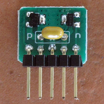
Here is a close-up of one of the two boards I soldered (the one with the worst alignment—see the pFET at the top left).
I spent the rest of the afternoon checking that the boards were OK. I used essentially the same setup as I used for Ron vs Vgs for pFETs and nFETS, with a 24Ω load and a 10V ramp that gradually turned the transistor off. Because the test was the same, I plotted the results together with the old results:

The PMV20XNER transistor has a much lower threshold than the other nFETS I’ve looked at, but a comparable Ron to the other power nFETs.

The SSM3J332R pFET also has a low threshold voltage and the on resistance is in the same range as others we have used in the past.
It looks to me like the half-H-bridge will be a perfectly reasonable way for the students to get FETs for the class-D amplifier. The current will be somewhat limited by the power dissipation of the pFET, but with an 8Ω speaker and 0.1Ω pFET, the power to the loudspeaker should be 80 times the power lost in the pFET, so the 10W limit on the loudspeaker should be reached well before the half H-bridge overheats.
Update: the EAGLE and Gerber files for this board are available at https://users.soe.ucsc.edu/~karplus/bme51/pc-boards/

")
 or hardback ($198)")


Love these blog posts! Keep them coming!
Comment by Rich — 2018 January 4 @ 00:49 |
I don’t know whether your students will bless me or curse me, but I’m glad it worked, including the tape suggestion! One more thing worth considering is flux pens; if they aren’t already in the kit, they really help with getting good joints when doing SMT hand soldering.
If someone is ever using these half-H-bridge prototype boards and wants to draw more power, maybe they could attach heat sinks to the reverse side of the board?
This post caused me to confirm that the footprint I used for the board I’m about to send off to be manufactured did indeed use the KiCad TO_SOT_Packages_SMD:SOT-23_Handsoldering footprint. I recreated the entire layout from scratch to improve heat dissipation after reading your post on designing these prototype boards.
Comment by Michael Johnson — 2018 January 7 @ 12:48 |
I don’t think that flux pens will be needed with this design—the lands are huge (1.2mm×1.4mm) compared to the leads, so just using flux-core solder seems to work fine. I don’t want to raise the price of the kit by $1.60 or more for just 4 solder connections. I didn’t even use my 0.4mm solder—0.8mm was fine. (I did’t try 1.6mm solder—that would be pushing my luck.)
I did plan the board so that heatsink could be stuck on the back, but the smallest heatsinks I have (1cm×1cm) are too big (1cm×5mm is as big as I could use). I’m not sure how much a heatsink would help anyway, as the junction-to-case thermal resistance is quite large for SOT-23s.
Comment by gasstationwithoutpumps — 2018 January 7 @ 13:59 |
[…] year we’ll be using the SOT-23 transistors, which are much cheaper, and soldering them to a breakout board. I’m a little worried about […]
Pingback by Long weekend, little done | Gas station without pumps — 2018 January 17 @ 10:02 |
[…] whether the nFET and pFET we’ll be using next quarter have small enough gate capacitances to be driven directly from a comparator, or whether we’ll […]
Pingback by Weekend off! | Gas station without pumps — 2018 February 25 @ 15:44 |
[…] course, I lied to you a little about what their circuit was—they were working with half-H-bridge boards that they had […]
Pingback by Inductive spikes | Gas station without pumps — 2019 May 10 @ 22:04 |